Topic last reviewed: 10 April 2013
Sectors: Downstream, Upstream
Solar thermal technology can be used in the oil and gas industry to generate process heat or steam. Solar energy collectors transfer the solar energy to a process fluid (typically water, oil or air), which is used directly (e.g. steam for enhanced oil recovery) or indirectly (e.g. heat transferred in a heat exchanger to another process stream).
Several different technologies can be used to heat a working fluid by sunlight. Solar thermal energy collectors are distinguished by their operating temperature (low, medium or high) and by their motion (non-concentrating or concentrating). Non-concentrating collectors (also called stationary collectors) are permanently fixed in place and do not track the sun. They have the same or almost the same area for intercepting and absorbing solar radiation; whereas concentrating collectors track the sun and generally have concave reflecting surfaces that intercept and focus the sun’s radiation on a smaller receiving area (Reference 1). Table 1 provides an overview of different types of solar thermal collectors.
Table 1: An overview of the different types of solar thermal collectors
| Motion | Collector Type | Absorber Type | Concentration Ratio | Indicative temperature range (°C) |
| Stationary | Flat plate collector | Flat | 1 | 30-90 |
| Evacuated tube collector | Tubular | 1 | 50-200 | |
| Compound parabolic trough | Tubular | 1-5 | 60-240 | |
| Single Axis | Parabolic trough | Tubular | 60-90 | 60-390 |
| Linear Fresnel | Tubular | 50-170 | 150-450 | |
| Two-axis tracking | Parabolic dish | Point | 100-1000 | 100-900 |
| Central receiver | Point | 100-1000 | 300-900 |
If lower temperature hot water is required, flat plate collectors (FPCs) or evacuated tube collectors (ETCs) can be used. FPCs feature a highly absorptive plate that conducts heat to tubes carrying the heat transfer fluid. ETCs feature heat pipes that absorb solar radiation and transfer the heat to a liquid (e.g. methanol) within the pipes. The liquid vaporizes and the vapour travels up the pipe where it condenses at the tip, releasing latent heat. The heat pipes are housed in vacuum-sealed tubes that reduce heat loss and allow the collectors to operate at higher temperatures than flat plate collectors (Reference 1).
Temperatures greater than those attainable by non-concentrating collectors can be reached using concentrating collectors, since a large amount of solar radiation is concentrated on a relatively small collection area. Concentrating collectors are divided into single-axis tracking collectors and two-axes tracking collectors (Reference 1). Parabolic trough collectors (PTCs) and Linear Fresnel reflectors (LFRs) could range in peak capacity from 1 MWth to several hundred MWth. If process heat requirements exceed 450°C, a central receiver system (heliostat field collector), which might range in size from approximately 30–560 MWth per tower at peak capacity, or a dish system (for small applications) are the only realistic technologies.
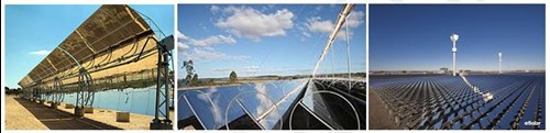
Figure 1: Images of high temperature solar collectors. From left to right: parabolic at the National Solar Energy Center, Israel; Areva Solar’s linear Fresnel reflector system; and eSolar’s central receiver system. Pictures from www.wikipedia.org.
Thermal storage can also be used for each of these technologies to decouple solar absorption from heat transfer to the process fluid. For hot water heating, a thermal storage module would consist of a water tank much like a household hot-water heater tank. For systems with temperatures up to 550°C, molten nitrate salt can be used as a heat transfer fluid for storing sensible energy (Reference 2).
More detailed information for these technologies can be found at the following locations:
- Flat plate collectors: http://www.powerfromthesun.net/Book/chapter06/chapter06.html
- Evacuated tube collectors: http://greenterrafirma.com/evacuated_tube_collector.html
- Parabolic trough collectors and thermal storage: https://www.nrel.gov/csp/
- Linear Fresnel reflectors: http://www.physics.usyd.edu.au/app/research/solar/clfr.html
- Heliostat Field collectors: http://www.powerfromthesun.net/Book/chapter10/chapter10.html
- Parabolic Dish reflectors: http://www.solarpaces.org/CSP_Technology/docs/solar_dish.pdf
Technology maturity
| Commercially available?: | Yes |
| Offshore viability: | No |
| Brownfield retrofit?: | Yes |
| Years experience in the industry: | 5-10 |
Project examples in the industry
- 21Z Solar Project, McKittrick, CA and Petroleum Development Oman—enclosed parabolic trough
- Coalinga Project, Coalinga, CA—heliostat field
Additional notes
Commerically-available technologies: stationary collector; parabolic trough; linear Fresnel reflector; and central receiver systems
Key Metrics
Range of application: | Potentially up to 500+ MW thermal capacity |
| Efficiency: | Dependent on technology and application |
| Guideline capital costs: | Highly dependent on technology and application (installed solar thermal can vary from as low as USD 83/m2 to USD 1,200+/m2 (2005 costs). NB: where m2 is the solar array area. |
| Guideline operational costs: | On the order of 1–2% of capex per year |
| Typical scope of work description: | Installing a solar collector to generate heat for steam generation or water heating would typically involve the following tasks:
|
Decision drivers
| Technical: | Footprint: large area of flat, contiguous space is required for a large installation. Intermittency: the solar resource is intermittent so storage or a second means of steam generation must be available for uninterrupted steam generation. |
| Commercial: | Premium for renewable steam generation: government incentives may be available. Fuel costs largely dictate the cost of steam generated from combustion relative to steam generated from solar thermal systems. Cases where fuel costs are high and where government solar incentives are available would likely be more amenable to use of solar. Available sunlight (insolation): greatly affects the overall cost of steam. A site with high direct normal irradiance, and a large area of available space (e.g. Chevron Coalinga project uses mirrors over 65 acres for 29 megawatts thermal (MWth) of peak steam production – see case study below). |
| Environmental: | Design for weather: wind, storms/sand storms, winter (e.g. subzero) and other severe weather events—this can increase the cost of installation and maintenance. |
Alternative technologies
The typical baseline alternative to steam/electricity generation by solar thermal is steam generation or cogeneration of heat and power by combustion of natural gas or other fossil fuels.
Operational issues/risks
Small hot-water systems tend to be relatively low-risk installations, whereas large high-temperature systems may carry higher risks depending on the application.
Some general technology risks include:
- Inaccurate irradiance data or variations in local weather over several years
- Extreme weather events, or other environmental conditions (e.g. high particulate loading in storms in some applications such as desert conditions)
- Conflict with environmental or cultural groups opposing disturbance of the desired site
- Water quality issues for steam and hot water applications
- Long-term impact of intermittency on balance of plant and ability of back up thermal load control system to respond to these fluctuations
Some potential risks related to new technology applications include:
- Unproven long-term demonstration of technology in successful applications
- Rapidly evolving technology
- Financing may be difficult because lending institutions perceive higher risk
Industry case studies
Solar thermal demonstration project, California (Reference 16)
The Chevron Coalinga solar thermal project, commissioned in 2011, produces steam for enhanced oil recovery (EOR) in California. The project uses heliostat technology from BrightSource Energy, Inc. to reflect sunlight from 3,822 heliostats (mounted mirror systems) focused on a 327 foot solar tower to generate steam.
Baseline scenario: Base design for steam production is an equivalent output natural gas-fired steam generator.
Energy efficiency project activity: Install solar thermal project using heliostat technology to provide 29 MWth steam to displace an equivalent quantity of natural gas-generated steam.
Performance specifications:
- Peak steam production: 29 MWth (megawatts thermal)
- 27% capacity factor
- Electrical output equivalent: approx. 13 MWe (megawatts electric)
- Tower height: 327 feet
- Number of heliostats / mirrors: 3,822 heliostats; 7,644 mirrors
- Facility size: 100 acres, with mirrors covering 65 acres
Estimated cost savings:
- The cost savings depend largely on the cost of natural gas. At a peak steam production rate of 29 MWth, the saving in natural gas to generate steam is estimated at around 120 MMBtu/hr or 120 Mscf/hr. The annual average production rate will be lower.
- The resulting steam will be produced emissions free, not counting the emissions associated with the construction and maintenance of the equipment. The greenhouse gas (GHG) emission reductions compared to natural gas-fired steam generation would be on the order of around 6 tonnes CO2 equivalent per hour.
References:
- Kalogirou, S.A. (2003). Solar thermal collectors and applications. In 'Progress in Energy and Combustion Science’, 30 (2004), 231–295.
- Energy Alternatives India (EAI) (website): ‘Concentrated Solar Power’.
- Weiss, W. et al. (2005). ‘Solar Heating Worldwide’. IEA Solar Heating and Cooling Program, Internal Paper 2005.
- NREL (website): ‘TroughNet’ — U.S. Parabolic Trough Power Plant Data’. National Renewable Energy Laboratory.
- NREL (website): ‘Linear Fresnel Reflector Projects
- Tubosol PE2, News Release, 4 May 2011: ‘World’s Largest Fresnel Solar Power Station Achieves Financial Close’.
- Areva Group (website): ‘A bright future for concentrated solar power (CSP)’.
- NREL (website): ‘Power Tower Projects’.
- DeLeon, P. and Brown, K.C. (1982). Solar Technology Applications to Enhanced Oil Recovery. In ‘Energy Sources’, Vol. 6, Issue 1–2, 1982.
- Gorman, D.N. (1987). ‘Assessment of central receiver solar thermal enhanced oil recovery systems’. Energy Citations Database (ECD), 1 July 1987.
- Hall, C. (2011). ‘Opposites Attract: Solar Powered Oil Wells’. EnergyDigital—Global Energy Portal (website), 1 December 2011.
- GlassPoint (website): ‘Lowest Cost for Steam EOR’.
- Helman, C. (2011). Oil From The Sun. In ‘Forbes’ Magazine, 25 April 2011
- Oil and Gas Journal (website): ‘PDO to pilot solar EOR in Oman’. 4 August, 2011.
- Reuters (website): ‘GlassPoint Unveils First Commercial Solar Enhanced Oil Recovery Project’. Press Release, 24 February 2011.
- Goossens, E. (2011). ‘Chevron Uses Solar-Thermal Steam to Extract Oil in California’. Bloomberg (website), 3 October 2011.
- Abengoa Solar—Solar Power for a Sustainable World (website): Industrial applications (No longer available)
- Areva Group (website): ‘Areva and Technip to Work on Solar Thermal (CSP) Applications for Oil and Gas Industry’. Press Release, 24 April 2012.
- IPCC (2011). ‘Renewable Energy Sources and Climate Change Mitigation: Special Report of the Intergovernmental Panel on Climate Change’. Cambridge University Press, Cambridge (UK) and New York (USA).