Topic last reviewed: June 2023
Sectors: Upstream
Introduction
Oil and gas wells generally achieve their highest production rates at the beginning of the production cycle, after which there is a natural decline. Most wells produce in a predictable pattern called a decline curve. Depending on the underground pressure, the natural flow of oil and gas can last for years. When the pressure differential is insufficient for the oil to flow naturally, artificial lift (AL) systems can be used to bring the oil to the surface. AL systems can also be used to dewater gas wells or heavy oil reservoirs to improve production.
AL design, selection, operation, and optimization are complicated topics. Many factors can influence the energy efficiency, carbon footprint, and carbon intensity of AL systems. The discussion here is meant to increase understanding of the more impactful factors affecting performance of the most common AL systems. While most of the information shared in this document is based on onshore AL systems, similar guidance would apply to applicable offshore sea/ocean floor well systems.
The most common AL systems include sucker rod pumps (SRPs), progressive cavity pumps (PCPs), electrical submersible pumps (ESPs), gas lift (GL), and downhole hydraulic pumps (DHPs). Each form of AL has advantages and disadvantages. Table 1 shows the typical operating ranges for different AL systems.
| Sucker Rod Pump | Rod-Driven Elastomeric Progressive Cavity Pump | Rod-Driven Metal-to-Metal Progressive Cavity Pump | Electric Submersible Elastomeric Progressive Cavity Pump | Continuous Gas Lift | Plunger Lift | Hydraulic Pump | Electric Submersible Pump | |
|---|---|---|---|---|---|---|---|---|
| SRP | RD-PCP | RD-M2M-PCP | ES-PCP | GL-C | PL | HP | ESP | |
| Liquid Rate (blpd) | 5000 | 5-5000 | 350-2500 | 5-5000 | up to 80,000 | Vert: 1-100 Horiz: 1-400 bbl/mmscfd | 25-4,000 | 50-150,000 |
| Depth (ft TVD) | 100-10000 | 100 - 9000 | 100 - 3500 | 100 - 8000 | 1000 - 15,000 | <5000 | < 15,000 | <15,000 |
| Build Angle (deg/100') | 10°/100' | ~5°/100' | ~5°/100' | ~5°/100' | NA | ~30°/100' | ~15°/100' | ~6°/100' |
| Max Deviation at Pump Depth (deg) | ~70-85° | 90° | 90° | 90° | NA | 30-50° | 40-70° | 90° |
| Fluid Temperature (deg F) | 550 F | 185 F | up to 600 F | 185 F | up to 350 F | 130-500 F | 250 F | up to 550 F |
| Corrosion Handling | Good to excellent | Good | Good | Good | Good to excellent | Excellent | Good | Excellent |
| Gas Handling | Fair to Good | Good | Good | Good | Excellent | Excellent | 100-1500:1 GLR | Good |
| Solids Handling | Fair to Good | Good | Poor | Good | Excellent | Fair to Excellent | Poor | Fair |
| Aromatics Tolerance | Excellent | Poor | Good | Poor | Good | NA | 20-50 API | Good |
| Fluid Viscosity (cP) | 1-5000 cp | 1-5000 cp | 1-5000 cp | 1-5000 cp | 1-500 cp | <50 cp | 1-500 cp | 1-500 cp |
| Location | Onshore | Onshore | Onshore | Onshore Offshore | Onshore Offshore | Onshore Offshore | Onshore | Onshore Offshore |
| Servicing Method | Flushby or Rig | Service Rig / Pulling Unit | Service Rig / Pulling Unit | Service Rig | Slickline / CT | Wireline | Hydraulic or Wireline | Rig or Rigless (WL, CT, etc.) |
| Minimum Producing BHP (FAP = ft TVD fluid above pump) | 0' FAP | 100' FAP | 100' FAP | 100' FAP | 2.5 ppg equivalent | 0' FAP | 100' FAP | 250' FAP |
| Prime Mover / Power Source | Gas or Electric | Electric | Electric | Electric | Gas or Electric | Natural Reservoir Energy | Electric | Electric |
| Overall System Energy Efficiency (%)2 | 45% - 60% | 70% - 80% | 35% | 75% - 85% | 10% - 30% | NA | 20% - 35% | 30%-70% |
Notes:
1. This table is not intended to show absolute technical limits of a particular lift method. Technical limits and recommended operating conditions for any given artificial lift technology will vary by manufacturer. Technology evolves and boundaries can change. Additionally, mitigations (e.g., gas separators and corrosion or abrasion resistant design) exist for some lift methods to mitigate the effects of challenging conditions, thereby extending the range and applicability of the lift method.
2. System energy efficiency is identified later in this paper. This table is not intended to be used as a direct comparison of energy efficiency performance between lift methods. Design, environment, and operating conditions play a large role in determining performance. A system which is highly efficient under one set of conditions may be unreliable or unable to function in another set of conditions. Energy efficiency comparisons between lift methods are only valid when systems are modelled and evaluated under identical conditions. If well-designed and operated, system efficiency usually falls within the ranges given in the table. If poorly designed or operated, or operated in challenging conditions for the technology, system energy efficiency can be significantly lower than the normal range.
3. FAP = fluid above pump; TVD = true vertical depth; BHP = bottom hole pump; WL = wire line; CT = coiled tube.
Selection of the best artificial lift method for a specific set of conditions involves consideration of multiple factors [References 1, 2, 3]:
- Reservoir parameters, including depth, pressure, temperature, productivity, gas-oil ratios, fluid composition and viscosity, decline rate, and so on.
- Wellbore construction, such as casing and tubing diameter, deviation, dogleg severity, sand control method, etc.
- Deployment or servicing method: tubing, slickline, sucker rod.
- Economic parameters: production rate, capital cost, operating cost, servicing cost, etc.
- Lifecycle artificial lift needs: consideration that the lift system which is best today might be poorly suited for well and reservoir conditions later. Oftentimes several lift methods will be necessary over the decades-long lifespan of a well. Synergies between successive lift methods can be important. For instance, it may make little sense to make large investments today in a gas lift compressor and gas distribution system if the next lift method for the well is likely to be an electrically powered SRP. A better choice for today’s lift technology may be to build out the electrical power distribution system and use an ESP.
- Knowledge and experience of the operating teams.
- Reliability.
- Equipment standardization and availability.
- Power source.
- Onshore/offshore.
Energy efficiency of artificial lift systems
The energy efficiency of AL systems can be calculated as the actual energy consumed relative to the theoretical energy to lift a volume of liquid with a given specific gravity and depth [Reference 4],
System energy efficiency= (actual energy consumed per volume liquid)/(theoretical lift energy per volume liquid)
Historically, energy efficiency has been a relatively minor factor affecting AL selection. In cases where two lift methods were otherwise equally suitable, energy efficiency might have been the deciding factor in selection. However, generally an AL method was selected based on production-related requirements and only afterwards would the design and operational performance be optimized for efficiency.
Continuing to optimize the AL system for reliable production over the life of the well, by following best practices described in the next several sections of this document, should help ensure acceptable energy efficient performance. However, if production conditions (e.g., fluid production rates, pressure, temperature, composition, water-oil ratio, gas-oil ratio, recovery mechanism) change significantly, then the AL system design should be re-evaluated.
In addition to production conditions, real-time monitoring of AL-specific key performance indicators (KPIs) can also trigger the need for re-optimization. Examples of these KPIs are listed in the Key Metrics section of this document. Ideally, all systems should have remote sensing and data visualization for real-time optimization.
Comparisons made solely on energy efficiency should be made with caution: context is important. Methodologies and scopes for quantifying carbon impact of various artificial lift methods have not been standardized. Efficiency comparisons between lift methods are only valid when both systems are evaluated in the same well, under the same conditions. The types and conditions of wells in which the SRPs are installed are different than wells in which ESPs are installed. Thus, no conclusion about energy efficiency can be drawn. In addition to the efficiency considerations described below, the following references can also be consulted [References 5,6].
Additionally, various power sources are often available to power artificial lift equipment, including grid power, diesel fuel, and natural gas. Each of these sources has their own carbon emission factor. As discussed further in the Energy efficient design document, the lowest carbon source of power should be used.
General energy efficiency recommendations
- Maximize primary production for as long as possible, leveraging reservoir pressure for lift.
- Reduce the amount of produced water by selective shut-off or use of inflow control devices.
- Select more efficient motor types such as NEMA (National Electrical Manufacturers Association) B induction motors or permanent magnet motors (PMMs). This may result in a trade off with other characteristics, such as torque for improved efficiency. Consider swapping technology over the life of a well as production rates and conditions change (for example, from ESP to PCP or SRP).
- Use appropriately sized motors to operate in the region of highest efficiency as illustrated in Figure 1 from the US Department of Energy. Consider motor size over the life of a well as production rates and conditions change (that is, decline).
- Reduce tubing friction through optimization of tubing size, proactive measures to manage tubing accumulations which restrict the internal diameter (scale, asphaltenes, paraffin), and decreasing the volume of unwanted fluids (water, associated gas, excessive gas lift gas). Ideally, unwanted fluids (especially gas) should be separated downhole as much as possible.
- Reduce backpressure by removing bottlenecks and reducing the pressure in the surface pipes and equipment.
- Improve inflow by conducting chemical treatments to remove skin damage or increase permeability of the reservoir rock.
- Using foaming agents and corrosion, paraffin, and scale inhibitors to help optimize production rates [Reference 7].
- Install variable speed controllers (such as variable frequency drives (VFDs)) to better match equipment performance to well capacity. Use of VFDs can increase harmonic distortion in electrical distribution grids, but this can be managed by harmonic filtering.
- Improve system reliability by taking actions to understand failure causes, prevent recurrence, and reduce carbon impact of well interventions.
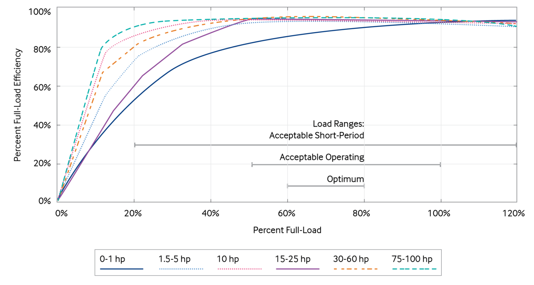
Figure 1: Motor part-load efficiency (US Department of Energy, 2014)
Specific considerations for each method of artificial lift
Sucker rod pumps
Sucker rod pumps are low shear downhole positive displacement piston pumps, which function by linear reciprocating action. They consist of a sucker rod string, a plunger, barrel, travelling valve, and standing valve (see Figure 2). Upward and downward action of the sucker rod string transmits energy from the surface unit to the plunger of the downhole pump. Power for the upstroke is supplied by the surface unit. Power for the downstroke comes from gravity and the weight of the rod string. Various forms of surface units exist, including conventional crank and beam balanced units, air balanced units, mark and reverse-mark units, long-stroke belt units, and hydraulic lift units. Power to the surface unit is usually supplied by an electric motor, but gas engines can also be used.
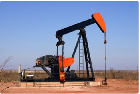
Figure 2: Beam or sucker rod pump
When well designed and operated, sucker rod pumps are very efficient. Actions that improve the efficiency of a sucker rod pump include:
- Sizing: properly designing and sizing the equipment for the application.
- Balancing: balancing the unit such that motor does not struggle to lift the rods, or to lift the cranks. When well-balanced, a smaller motor is needed than when the unit is significantly out-of-balance.
- Effective stroke length: maximizing effective stroke length by: (1) operating with as long of a stroke length as possible to reduce the percentage of stroke lost to rod stretch, and (2) anchoring the tubing to prevent upward/downward movement of the tubing and standing valve.
- Spacing: spacing out the pump near the bottom to increase compression, improve traveling and standing valve action, and reduce gas interference and gas lock.
- Pump slippage: monitoring for traveling and standing valve leaks and taking timely action to repair slipping pumps.
- Gas separation: positioning the pump or designing the completion to reduce gas ingestion into the pump.
- Pump off controllers (POC)/dynamometer: operating SRPs with POCs to reduce fluid pound and daily run time.
- Variable frequency drives (VFDs): Using VFDs to enable real time speed control, especially when paired with a POC. VFDs can also be used with NEMA B motors, which offer higher efficiency but lower starting torque than the NEMA D motors which are more commonly in sucker rod pumping.
- Active front-end (AFE) regeneration: Using AFE technology coupled with VFDs to regenerate power from the SRP downstroke into the grid, resulting in modest (less than 10%) net power savings, while reducing harmonics generated by VFDs. Regeneration is an energy-saving improvement compared to the typical dynamic braking resistors (DBRs) that are used to absorb generated power in an SRP system. Some newer SRP power saving techniques are being created that take advantage of local power storage and usage (such as a capacitor bank tied into the DC bus of VFDs on the same pad).
- Stuffing box: ensuring the stuffing box is not overly tight to reduce unnecessary friction. Stuffing box leaks can lead to methane emissions.
- Rod centralizers: using rod centralizers to mitigate coulomb friction, especially in deviated wells.
Progressive cavity pumps
Progressive cavity pumps are low shear positive displacement downhole pumps which operate by the low speed (approximately 50-500 rpm) rotation of a rotor inside a stator (see Figure 3). In its simplest ‘single lobe’ form, the rotor has a circular cross section and helical shape. The stator is a metal tube having a double helix internal bore. The rotor installed inside the stator, creates seal lines where the rotor and stator meet. The tightness of the seal line (and number of seal lines) is what generates head or pressure capacity of the pump. The empty volume between the single helix rotor and double helix bore of the stator between two seal lines is called a cavity. The size of the cavities and rotational speed (RPM) are what determine the volumetric capacity of the pump. Rotation of the rotor inside the stator causes the cavity (and the fluid contained therein) to travel upwards in a helical fashion, moving fluid from the intake end of the pump to the discharge end.
Various drive systems are available for PCPs. The drive selection process should include design, technical, and operational factors, including energy efficiency.
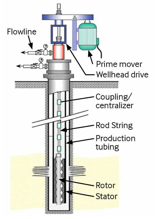
Figure 3: Progressive cavity pumps
Surface drives/rod driven PCP
Direct drive surface units using a PMM and VFD are the most efficient. Most common is the belt-and-sheave style drive head installed on top of the well, with the power source being an electric (induction) motor. With this style of head, speed control would require a sheave change or VFD. Excluding the motor, the belt-and-sheave style drive head is slightly less efficient than a direct drive unit. Hydraulic drive heads are sometimes used to give speed control without the need for a sheave change or VFD. Here, speed is regulated by recirculating some of the pressurized hydraulic fluid back to the hydraulic fluid reservoir. Recirculation of power fluid is inherently inefficient.
Downhole drives/ES-PCP hybrid
Direct drives with permanent magnet electric submersible motors can be used and are generally more reliable and efficient than an induction ES motor paired with a downhole gearbox. In deep, deviated wells, with high viscosity fluids, bottom-drive ES-PCP systems can be more efficient than rod-driven systems. These hybrid systems facilitate the handling of viscous and abrasive fluids, increase flow rate, and diminish costs. Advantages also include elimination of tubing wear by removing the rod string, greater torque capacity, lower surface maintenance, and less frictional losses thereby lowering power requirements. However, the trade-off comes from expensive downhole components, namely the motor, motor protector, power cable, and downhole gearbox (if any), which have limited run-lives. Surface drive systems are more easily maintained and repaired and are not subjected to severe downhole conditions of pressure, temperature, and well fluids which can cause the failure of submersible drive systems.
Being positive displacement in nature, PCPs can have high volumetric efficiency and high energy efficiency in the right circumstances. High efficiency is not guaranteed. Design, operation, and well conditions all have an impact. Factors which influence the efficiency of PCPs include:
- Pump tightness and slippage: pump tightness affects slippage and friction torque. Both are forms of wasted energy, and there is a compromise between the two. Tighter pumps operate with more friction torque (which increases stress on the elastomer and reduces run life) but are more efficient. Pump tightness is best managed by elastomer-fluid compatibility testing and establishing tightness criteria for pumps, and bench testing each pump to ensure it falls within the acceptable tightness range before installation.
- Pump speed and differential pressure: slippage is normal and expected in a PCP. The slippage rate is roughly linear with differential pressure, and for any differential pressure, is independent of RPM. When operated at low RPM or high differential pressure, slippage will consume a greater percentage of the pump’s capacity, and result in lower volumetric energy efficiency.
- Viscous torque: viscous torque is viscous friction in the pump. It is the pressure or torque required for the rotor lobes to push the fluid through the pump cavities from the intake end to the discharge end of the pump. If the viscosity is high and the cavities are long and narrow, viscous torque can be high. For high viscosity fluids, large diameter, highly eccentric, short pitch length, single-lobe pumps are used to minimize viscous losses in the pump.
- Rod frictional torque: rods rotating in fluid and metal-to-metal contact of the rod string with the tubing are other sources of friction that reduce energy efficiency. Rotating in water, rod frictional torque is low and usually only a few percent of total torque. In design cases, it is not uncommon for the friction torque to be ignored. In highly viscous fluids, rod frictional torque can be significant. Where it is significant, rod frictional torque is not easily mitigated except by converting to an ESP-PCP system.
- Gas separation: similar to an SRP, gas entering a PCP should be minimized as it consumes pump space and reduces efficiency. While PCPs will not typically gas lock, the elastomer is sensitive to gas. Excessive gas can cause too much heat in the pump and quickly damage the elastomer. Pumpoff is to be avoided.
Electric submersible pumps (ESP)
Electric submersible pump (ESP) systems employ a centrifugal pump below the level of the reservoir fluids, connected via electric cable to a surface source of electricity. Figure 4 shows a schematic of the ESP.
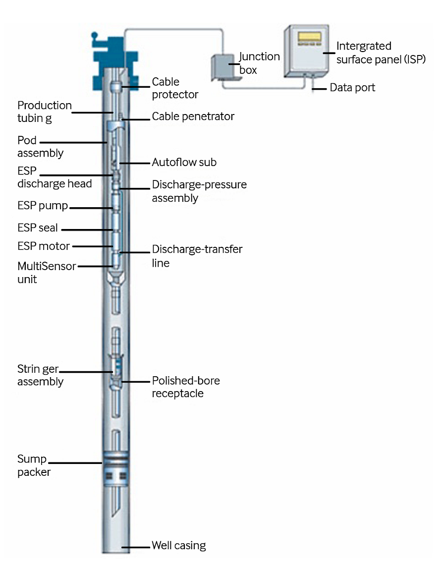
Figure 4: Electric submersible pump (source: Schlumberger)
Electrical submersible pumps consist of an electric motor (PMM or IM), a seal which protects the motor from the ingress of well fluids, a gas separator (optional) to remove free gas before it enters the pump, and a pump. ESPs operate at high speed (typically 1,500-7,000 RPM) and impart a high amount of shear on the produced fluids. Fluid shear is a form of energy loss.
The most common ESP configuration involves a centrifugal pump which generates head by spinning the fluid outwards using an impeller to create centrifugal force and velocity. Fluid is then deflected inwards towards the axis of the pump using a diffuser to convert velocity into pressure. Multiple stages of impellers and diffusers are used to generate enough head to lift fluid to the surface.
A variant of the ESP is the helical pump. This pump consists of an auger shaped rotor spinning inside a stator. Helical pumps are somewhat lower shear than multi-stage centrifugal pumps, giving them a small advantage in high viscosity conditions. Both varieties ESP (centrifugal or helical) are still high RPM and high shear compared to SRP and PCP.
ESPs are centrifugal pumps – the fluid is not contained. Continuous rotation (power) is required to maintain pressure. PCPs and SRPs are positive displacement (PD) pumps, meaning fluid is contained in a confined space. Continuous motion is not required to maintain pressure in PD pumps. This important difference makes centrifugal pumps less efficient than their positive displacement cousins. Properly designed and operated, ESPs will have only moderate energy efficiency.
Two factors most impact the energy efficiency of ESPs:
Design
ESP systems have an operating window and are usually designed to operate near the best efficiency point within the window. Operating outside the design window can cause upthrust or downthrust wear and shorten the pump life. Sometimes backpressure is increased at the surface to keep the pump inside the operating window. If the pump is sized to meet the lift requirements, there is no need to apply additional backpressure. In most cases, ESPs should be run with VFDs to ensure operation in the design window as reservoir conditions change. An exception is when the reservoir conditions are known and unchanging and on/off control of the ESP will result in optimized production (that is, a constant production waterflood well).
Gas or gas volume fraction (GVF)
As with other downhole pumps, free gas entry into the ESP is undesirable, as the pump needs to spin faster/work harder to lift the same amount of liquid. Because centrifugal force is a function of fluid density, free gas also reduces the head capacity of the pump. Reduced head generation results in reduced flow rate and efficiency. Gas lock can occur if the pump contains so much gas that it is unable to lift fluid to the surface. Mitigation options for gas lock include:
- Installing the pump below all perforations to encourage gas to flow up the annulus, and liquid to flow down to the pump intake. In this configuration, a motor shroud will be needed to direct flow downwards, past the motor, for cooling. If installing in the rathole is not possible, the pump should be installed as deep as feasible. Deep installation will increase the intake pressure and reduce the GVF at the pump intake depth.
- Adding a rotary gas separator to the design. Rotary gas separators use centrifugal force to cause partial separation of the phases, with the denser phases being directed into the pump, and the less dense gaseous phase being discharged into the annulus above the pump intake.
- Adding a gas handler to the design. Gas handlers function by compressing the fluid and driving some of the free gas back into the solution.
- Ensuring the pump is always operated with sufficient fluid above the pump intake.
Gas lift
In gas lift (GL), compressed gas is injected down the casing tube annulus of a production well, entering the well at numerous entry points called gas lift valves (see Figure 5).
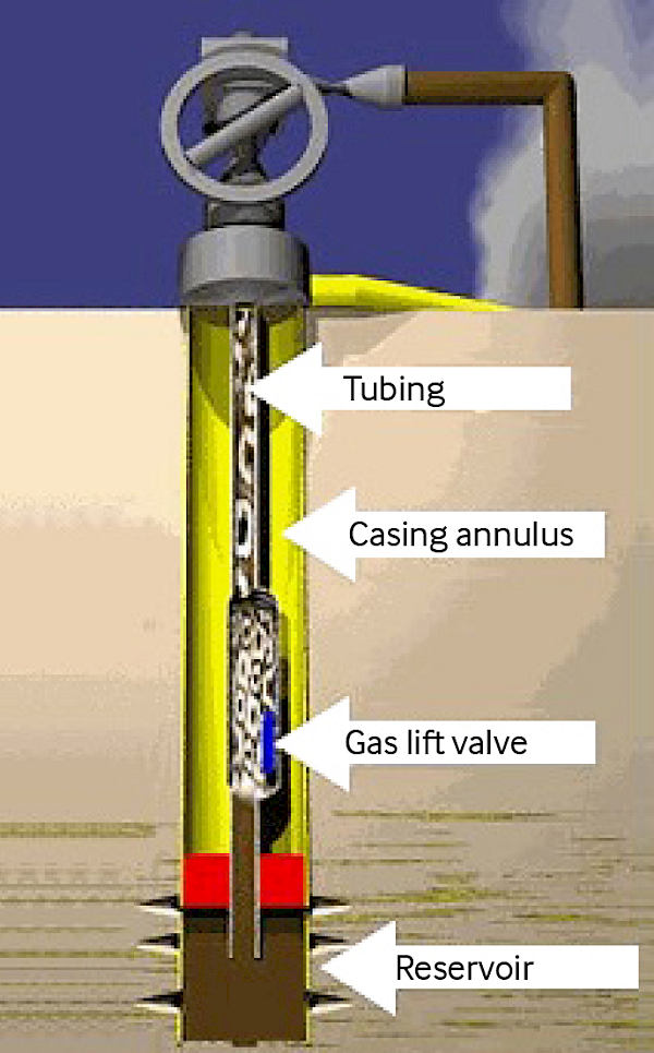
Figure 5: Gas lift schematic (source: Tech Flo Consulting LLC)
GL involves injecting high pressure natural gas into the annulus of a well, through a GL valve, and into the tubing, to decrease the density of the tubing fluids. With the lightened fluid column, reservoir pressure can push liquid out of the well. GL usually involves the installation of a series of mandrels and GL valves in the tubing string, with the valve depths and opening/closing pressures predetermined through calculations and modelling. When initiating flow, the valves open and close sequentially from the shallowest valve to the deepest. When operating normally, all the shallow valves are closed, and gas is only injected through the orifice at the deepest possible mandrel location.
Historically, GL valves have been pressure operated. Recent advances in GL technology include electronically operated valves which have control lines running to the surface. With electronically operated valves, the operator controls which valves are open and closed. With pressure actuated valves, active control is not possible. Rather, pressure actuated valves open and close based on tubing pressure and casing pressure at the valve depth.
Unlike lift methods using pumps, in gas lifted wells, a free gas phase in the reservoir fluids aids in the lifting process. When free gas is present, less external energy is needed. However, unlike other AL systems, gas lift systems may have additional greenhouse gas (GHG) emission risks, including:
- Use of gas turbine or internal combustion engine mechanically coupled to the compressor. Depending on the utility grid GHG emission factor, these units may emit more GHGs per unit volume of gas compressed. Electrifying compressors and feeding them lower carbon power can help mitigate this issue.
- Potential for methane fugitive emissions in the gas lift system.
Opportunities to improve efficiency and performance of GL systems include:
- Compressor optimization: sometimes an imbalance exists between the amount of gas supply needed to support the wells, and the output of the compressor. This can result in the recycling of excess gas back to the compressor inlet. Recycling of compressed gas is wasted energy and should be minimized.
- Design optimization: factors such as reservoir pressure and temperature, productivity index, well test results, and production pressure, volume, and temperature information are key inputs to the wellbore model, affecting the initial design, the depths at which mandrels are installed, and the design opening pressure for the GL valves. As reservoir behaviour changes, models should also be periodically reviewed and updated to ensure the system is performing as expected.
- Backpressure reduction: GL performance is extremely sensitive to backpressure, more so than other lift methods. In addition to requiring more lift energy, increased backpressure reduces the downhole volume and effectiveness of any gas which is injected. For optimal performance, backpressure should be minimized. Backpressure debottlenecking methods include proper sizing of the production choke and operating the well with the choke fully open, ensuring the flowline has an inner diameter (ID) which is at least as large as the tubing ID, and reducing the operating pressure of production vessels.
- Surface system optimization: optimizing gas distribution system is also helpful for getting the best performance from the artificial lift system. Gas lift system pressure should be maintained at a high and constant value near the design pressure for all the wells in the system.
- Avoidance of shallow injection/multipointing: monitoring of well performance is needed to ensure the downhole valves are functioning as intended. Instability in GL system distribution pressure, solids/debris, poor initial design, or changing reservoir or well performance can cause suboptimal downhole injection. With pressure actuated valves, multiple valves could be open simultaneously (multipointing), injection could be unstable and oscillating between two different valves, or injection could be continuously going through a shallow valve with no injection at the intended depth.
- Injection rate optimization: one of the outputs of the GL wellbore model is an estimate of the optimal gas injection rate. Injecting too little gas will reduce lift efficiency and production. Injecting too much gas can increase production slightly but will reduce efficiency and have diminishing returns.
- Continuous vs. intermittent GL: continuous gas injection is not always needed. Sometimes gas is needed to kick off a well, after which the well will flow naturally. Other times, short duration shots of gas are periodically needed to increase the flow velocity to remove liquids which have accumulated in oil and gas wells.
- Plunger assisted gas lift (PAGL): as liquid production declines in GL wells, the ratio of injected gas to liquid produced increases. GL well efficiency declines in this manner. Adding a plunger to the system can help improve the lifting efficiency and reduce the gas injection needed in low-rate wells. A PAGL system is a form of intermittent gas lift that uses gas pressure build-up in the casing-tubing annulus to push a steel plunger, and a column of fluid above the plunger, up the well tubing to the surface. The plunger reduces fallback of liquids into the well as the fluid column travels to the surface, increasing overall efficiency compared to intermittent GL. No external power is required except to actuate valves.
Hydraulic pumping
Downhole hydraulic pumps differ from sucker rod pumps in that they are used to lift oil to the surface (see Figure 6). The power fluid is pumped from the surface into the well.
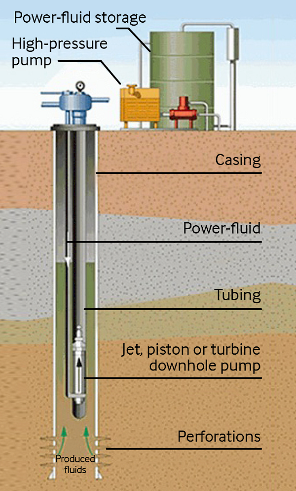
Hydraulic pumping is a type of artificial lift in which high pressure hydraulic power fluid is injected into the wellbore to provide energy to operate a downhole pump. Hydraulic pumping takes various forms, including piston pumps, turbine pumps, and venturi jet pumps. Injected fluids are produced back to the surface, meaning the total lift requirement is greater than the volume which is being produced from the reservoir. For jet pumps, the volume of injected fluid may be two or more times as high as the amount of liquid being produced from the reservoir. For this reason, jet pumps can be highly inefficient.
Downhole hydraulic pumping is uncommon in the oil and gas industry. This technology is mostly found in environments and wellbore geometries where other forms of artificial lift are unreliable Hydraulic lift can have moderate efficiency if the pump is positive displacement in nature, or very low efficiency for venturi pumps. Improving energy efficiency and carbon impact of hydraulic pumps is similar to gas lift. Under-injection of power fluid will reduce production and increase carbon intensity. Over-injection will consume more energy than is needed.
Key metrics
| Energy efficiency | Power consumption for artificial lift technologies is a function of the AL method, production, well depth, API gravity, and energy source. |
|---|---|
| Energy KPIs |
|
Note:
- Tvd: true vertical depth, i.e., actual depth from wellhead
- Bbl: barrel of oil equivalent
- Scf: standard cubic feet
Decision drivers
| Economic rule-of-thumb | For brownfield sites, a rule of thumb is to optimize the existing equipment first for energy efficiency, consider new proven technology second, then look at new technology last. For greenfield, the same order applies but design optimization and new proven energy efficiency technologies can be looked at in parallel. |
|---|
References
- Clegg, J. Petroleum Engineering Handbook, Volume IV: Production Operations Engineering, Society of Petroleum Engineers, Volume 4, 2007.
- Guo, B. Lyons, W. and Ghalambor, A. ‘Artificial lift methods’, in Petroleum Production Engineering, Gulf Professional Publishing, 2007.
- Brown, K. The technology of artificial lift methods. Volumes 1-4. 1980-84.
- Schmidt, C. ‘Benchmark for assessing the energy efficiency of artificial lifts.’ In Oil & Gas Automation Solutions, No. 5, February 2003.
- Hongkun, D. Helmers, P. and Reimers, Ø. 2019. ‘Reducing CO2 emissions through the selection of an energy-efficient artificial lift method’. 14th Offshore Mediterranean Conference and Exhibition. Ravenna, Italy. 27-29 March, 2019.
- Takacs, G. ‘Ways to obtain optimum power efficiency of artificial lift installations.’ In SPE-126544-MS. SPE Oil and Gas India Conference and Exhibition. Mumbai, India. January, 2010.
- Tennessen, R. ‘A comparison of the energy efficiency of various types of artificial lift systems.’ In Oil & Gas Automation Solutions, Number 2, November, 2002.
Other resources
- Useche-Narvaez, C. Montes-Páez, E. and Guerrero-Martin, C. ‘Evaluation of the carbon footprint produced by conventional artificial lift systems in a Colombian field.’ Journal of Petroleum Science and Engineering, Volume 208, Part E, 2022.
- U.S. Department of Energy 2014. ‘Determining electric motor load and efficiency.’2014.