Topic last reviewed: May 2025
Sectors: Downstream, Midstream, Upstream

Overview

Battery energy storage systems (BESS) use rechargeable battery technology, normally lithium ion (Li-ion) to store energy. The energy is stored in chemical form and converted into electricity to meet electrical demand. BESS technologies will support installations and businesses to overcome the energy trilemma to provide low carbon, affordable and reliable energy. BESS can help enable increased electrification of oil and gas facilities by improving onsite power generation efficiency and reliability and supporting the integration of intermittent renewable power from solar or wind. Key and unique features of BESS include1:

  • Ability to store excess or low-cost electricity produced, and discharge during high-cost hours (time of use) to improve plant load factor or plant economics
  • Immediate response to power demand fluctuations
  • Lower carbon intensity of onsite generation, and store excess power to be used when required
  • Less maintenance than rotating machinery
  • Modular/turnkey/scalable solution

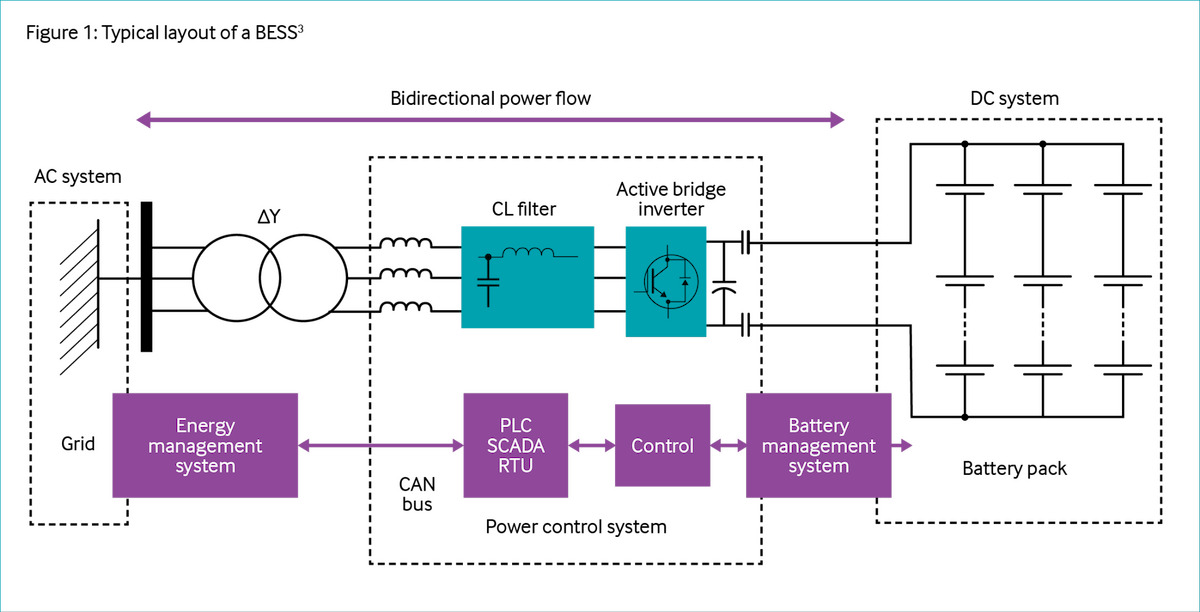
A BESS includes the following major elements:

  • Battery modules supporting structure/ racking and containers
  • Safety/fire suppression system
  • Battery management system (BMS)
  • Power conversion system (PCS) (bi-directional inverter)
  • Energy management system (EMS)
  • Transformer(s)
  • Connection to the power grid or internal electric system

BESS can also act as a buffer and support system. Key roles include:

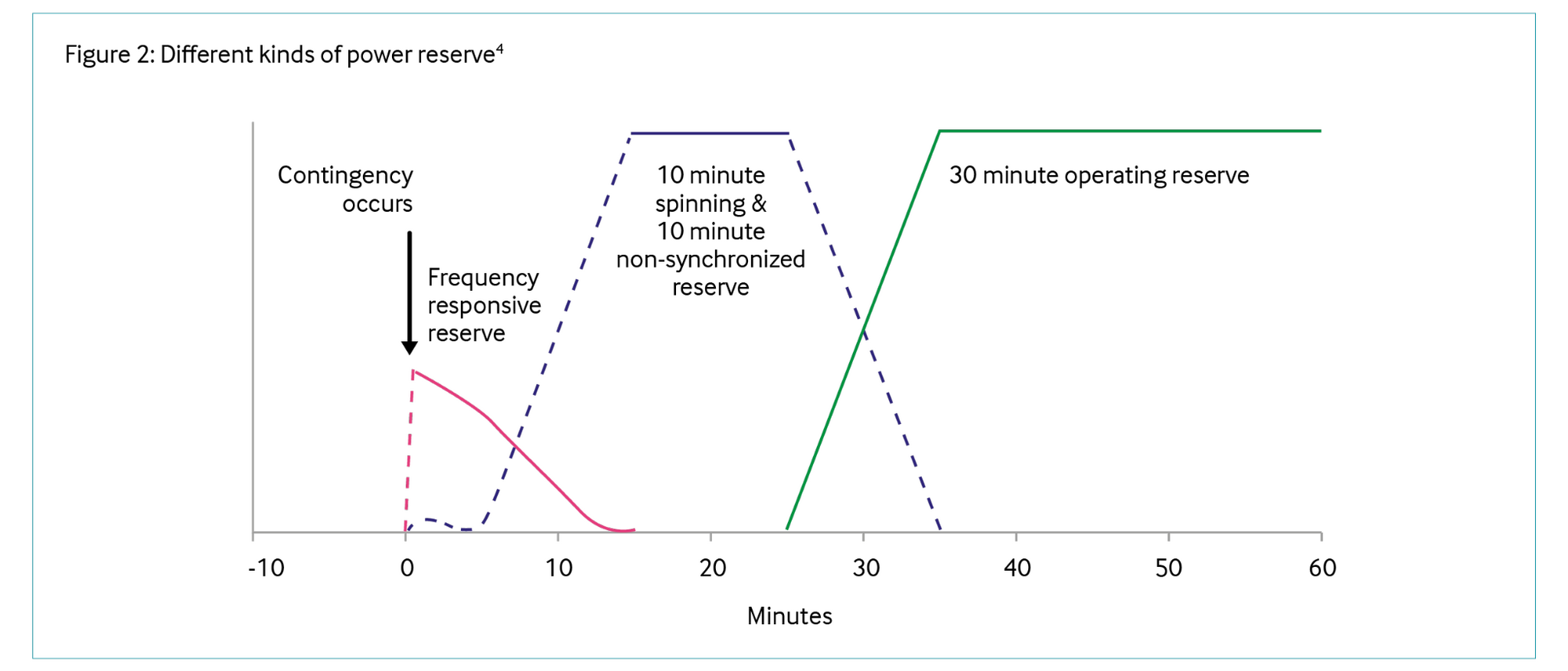
  • Spinning reserve: provide immediate power when demand spikes or during a turbine/generator trip
  • Primary power source support: in remote oil and gas operations where diesel or gas generators are the primary power source, BESS can store excess energy and provide backup power reducing generator run-time, improve fuel efficiency, and extend equipment life by reducing start/stop cycles. BESS can be used both in onshore and offshore settings, including both topside and subsea
  • Offshore subsea applications: provide reliable subsea power for critical control systems and sensors. Offshore applications are still in relatively early stages of maturity; subsea BESS systems greater than 1 MWh are only now being piloted2
  • Peak shaving: store excess energy generated during low-demand periods and discharge this energy during peak demand times, which is particularly beneficial for drilling rigs and completion sites that experience fluctuating power requirements. These systems help manage energy- intensive processes, such as rotating drill bits and powering surface equipment. The use of BESS can lead to improved operational flexibility and reliability. Systems can quickly respond to changes in energy demand, providing a stable power supply for critical operations. This responsiveness minimises interruptions that could lead to costly downtime and can reduce demand charges in cases where power is imported from a utility grid
  • Energy shifting: store excess energy generated during low-demand periods for later use
  • Ancillary services: for systems connected to the grid it helps maintaining grid operational stability and security. This is oken initiated as a separate commercial revenue stream for the asset
  • Frequency regulation: quickly adjust output to stabilize the grid frequency
  • Renewable source intermittency: use BESS to increase behind the meter capacity of solar PV or wind. By installing systems with nameplate capacity larger than the load of an upstream operation, a BESS can store the excess energy for use when the sun is not shining or the wind is not blowing. A BESS can also be used for energy arbitrage: e.g., generating low- cost solar power and then selling the excess to the grid to offset night-time purchases.

Technology description

Battery system layout

To understand the main characteristics of the BESS system, a general overview of the whole battery system is shown in Figure 1.

The BESS includes two parallel lines, and each line is composed of two battery systems, where energy is stored, two energy converters switchboards, which represent the interface components between the energy storage and the energy distribution line, and one transformer, used for voltage adaptation of the power supply. Due to their high modularity, battery systems can run in parallel line configuration, improving system flexibility and reliability. Lines can be switched on or off as needed or each line can run at partial load, increasing the degrees of freedom to control the system.

The three blocks shown in Figure 1 are the main components of the BESS, and each one should be designed to optimise the efficiency and the effectiveness of the overall system operation. Efficiency takes into account energy conversion system losses [kW] throughout the BESS lifecycle, including charging, discharging, and idle states. BESS capital cost should account for overall system acquisition and typically includes project integration and connection costs. Maintenance and operational costs are typically low since most BESS components are static subsystems.

Spinning reserve

In oil and gas upstream plants, power generation systems are normally designed to operate with N+1 generators running to enable a level of redundancy and guarantee a certain operating reserve. This means each generator is not at full load. The reserve power acts as a buffer which can supply any system load increase or alternatively if a running generator(s) should trip offline, then some or all the system loads can be sustained by the remaining online generation plus the reserve power that is available.

The operating reserve can be one of two types:

  • Spinning reserve: the amount of spinning reserve available within a power system, calculated as the difference between the generation capacity online and available, and the total electrical load
  • Non-spinning reserve (standby power generation): the extra generating capacity not currently connected to the power system, but which could be brought online quickly however, there would be a short delay to successfully synchronize with the grid frequency

Even if both spinning and non-spinning reserves must come online within ten minutes and run for at least two hours, the first one is slightly more reliable, since it is not affected by start-up issues. It can respond immediately when shortfalls occur. Non-spinning reserve generators, however, are initially offline, so they are typically adopted aker all spinning reserves have been used up.

Moreover, two other kinds of power reserves can be considered (see Figure 2), with respect to their activation time intervals:

  • Frequency response (or regulation) reserve, an ultra-fast power supply that immediately starts working when the failure occurs and must respond within ten seconds from the disruption to quickly restore the nominal grid frequency
  • Replacement (or contingency) reserve, which is slower, requiring longer start- up (generally 30 minutes or more)

Using a battery bank with the power generation unit reduces the spinning reserve, allowing users to rethink turbomachinery operations by switching off at least one gas turbine and increasing the load on the others. In this way, the efficiency of the machines will increase, with lower energy consumption, associated emissions and cost of electricity produced.

Since batteries have fast time response, on the order of milliseconds, they can replace spinning reserve. Without burning excess natural gas, the battery bank adapts to frequency variations with a high degree of stability, availability and efficiency. In fact, if a generator were to trip offline, the battery can quickly replace the lost energy capacity, until another gas turbine is switched on. In this configuration, spinning reserve is minimised and is only required when the battery system is unable to fully compensate for the total energy deficit from the power generation unit. However, with a suitable design of the storage device, the probability of this event is minimal. In addition, turbine utilisation is increased, resulting in higher efficiency, lower runtime and reduced maintenance costs.

Pros and cons of BESS

PROS

CONS

Improved grid stability

  • Rapid response: BESS can react to fluctuations in milliseconds, providing a buffer against sudden changes in demand or supply
  • Frequency regulation: BESS can help maintain a stable frequency, reducing the need for mechanical governor adjustments on turbines

High initial costs

  • Capital investment: the upfront cost of installing BESS, including batteries, inverters and control systems, can be significant
  • Integration costs: integrating BESS with existing turbine systems requires advanced control technologies and expertise, adding to initial costs

Enhanced efficiency

  • Optimised turbine operation: turbines can operate closer to their optimal load, reducing fuel consumption and wear. BESS manages short-term fluctuations instead of the turbines, avoiding inefficient ramping
  • Lower emissions and reduced fuel costs: by reducing the need for turbines to operate in inefficient part-load conditions and to handle fluctuations in power demand, BESS lowers overall fuel consumption and runtime, leading to significant cost reduction in fuel savings, maintenance, and emissions

Technical challenges

  • Complex system integration: seamless operation between BESS and turbines requires sophisticated control algorithms and communication systems
  • Safety risk: BESS require robust fire protection and containment designs to address the potential for thermal runaway and other hazards. Specialised training for emergency responders, including firefighters, is essential to ensure effective management of battery-related incidents, adding complexity and cost to the response
  • Brownfields integration challenges with BESS, e.g., changes to power management system, integration with heating ventilation and air conditioning systems

Higher renewable integration

  • Smoothing intermittency: BESS smooths out the variability of renewable sources, allowing for a higher penetration of renewables without compromising grid reliability
  • Energy shiking: excess renewable electricity can be stored and used when renewable generation is low, or demand is high

Maintenance and lifecycle

  • Battery degradation: over time, battery capacity can degrade, necessitating replacements and impacting long-term operational costs
  • Regular maintenance: both turbines and BESS require ongoing maintenance to ensure reliability and performance, though the nature of the maintenance differs (mechanical vs. electrical)

Enhanced reliability

  • Backup power: provides instant backup during turbine outages, improving overall system reliability and reducing downtime
  • Fast frequency response: acts as a ready reserve, reducing the need for keeping additional turbines running at low loads, which is inefficient and costly

Regulatory and policy constraints

  • Permitting and compliance: navigating regulatory landscapes for installation and operation can be complex, particularly in regions with strict environmental or energy regulations
  • Incentive dependencies: economic viability may depend on subsidies or incentives that can change with policy shifts

Energy arbitrage (for grid connected systems)

  • Low-cost electricity can be stored and used when electricity costs are high

Energy density and duration limits

  • Energy storage limitations: the amount of energy a BESS can store is finite, which might limit its effectiveness in longduration power outages or extremely high-demand situations
  • Discharge rates: while BESS can discharge quickly, the rate at which they can do so is limited by the inverter capacity and battery chemistry, potentially necessitating oversized systems to handle peak demands

Technology maturity

Li-Ion batteries are currently the reference technology for energy storage, with a high level of maturity and fully commercial.

They are characterised by high power density, high specific energy and efficiency and a versatility of applications. The oil and gas industry has been slow to adopt Li-ion, primarily due to the flammability of their chemistries. Industry efforts to improve BESS safety during a period of rapid deployment expansion have led to a sharp decrease in the failure rate5. While data suggests that many failures originate in the controls and the balance of the system rather than the battery cell itself, it is important to acknowledge certain limitations in root cause analysis. Identifying the precise initiation point of a failure is challenging, as physical evidence is oken destroyed in fires and available telemetry may be limited. Furthermore, all recorded failures did eventually result in thermal runaway and fire at the cell level. However, findings indicate that many of these incidents could be mitigated by following appropriate recommendations applied to current and future systems.

Key metrics

Range of application

Onshore: BESS are primarily used to optimise power management at drilling sites, often integrated with diesel generators. They help in reducing fuel consumption by allowing generators to run at optimal load profiles and provide auxiliary power during peak demands. This hybrid setup enhances overall asset utilization and reduces operational costs, emissions, and maintenance needs.

Offshore: the use of BESS is becoming more prominent on offshore platforms, where they are utilized to stabilise power systems, support intermittent renewable energy integration (e.g., wind or solar), and ensure efficient load management. This is critical in remote offshore environments to reduce reliance on diesel generators and improve sustainability.

Roundtrip efficiency85-90%
Energy key performance indicators
  • Energy density and capacity
  • Response time
  • Lifecycle cost
  • Expected life
  • State of health and state of charge
  • Depth of discharge
Typical scope of work description

Site assessment and integration: analysis of existing power systems to determine how BESS can be integrated effectively, whether as a standalone energy backup or in a hybrid configuration with generators.

System design and engineering: customised design to meet specific power requirements, including considerations for scalability and adaptability to future energy needs.

Installation and commissioning: deployment of battery packs, control systems and any necessary grid-tie equipment. This stage also involves rigorous testing to ensure reliable operation.

Operation and maintenance: continuous monitoring and maintenance to ensure optimal performance, along with software for energy management that can predict and adjust energy flows for maximum efficiency.

Decision drivers

Technical
  • Grid stability and reliability
  • Energy optimisation
Operational
  • Reduction of fuel consumption
  • Reduced maintenance and increased equipment lifespan
Commercial
  • Cost efficiency
  • Return on investment
Environmental
  • Decarbonisation and emission reduction
  • Sustainability goals

Alternative technologies

The following section presents an overview of two possible types of BESS used in the oil and gas sector, including their respective levels of technological maturity and distinctive characteristics. The subsequent table provides a concise summary of additional BESS types, highlighting their primary features.

It should be noted that there are numerous alternative energy storage technologies, such as thermal energy storage, compressed air storage and pumped hydro. However, these are not discussed in detail in this paper as they are more pertinent to long-duration storage, rather than the coupling of such storage with a power generation system.

 LI-ION BATTERIESFLOW BATTERIES (i.e. V, Zn-Fe)
TRL11 IEA (1-11)9 IEA (1-11)
Cycle life500 to 3000 cycles (up to 7000 for LTO)10,000 to 20,000 cycles
Round trip efficiency85 – 95%70 – 90%
Energy density150-300 Wh/kg5 to 25 Wh/kg
Reaction time< 1 sec< 1 sec
Pros
  • Store a large amount of energy relative to their weight and volume
  • Space and weight efficiency
  • Rapid charge and discharge
  • Shorter duration storage
  • Longer cycle life than Li-ion (~ 20 years vs 12 years)
  • Thermal stability
  • Long duration discharge
  • Environmental safety
Cons
  • Thermal runaway risk; requires fire prevention
  • systems
  • Limited cycle life; capacity fades over time
  • Performance drops in extreme temperatures
  • Lower energy density; larger land footprint
  • Higher upfront costs compared to Li-ion
  • Slower response time compared to Li-ion
  • Higher O&M costs

Operational issues, risks and opportunities

The deployment of BESS in classified hazardous areas presents specific operational challenges, particularly where flammable gases, vapours or dust are present. Effective thermal management has a critical importance, as any overheating caused by high energy demand could result in system failure if not properly maintained. It is essential to carry out regular maintenance to prevent battery degradation, especially in harsh industrial settings.

In such environments, there is a risk of ignition from the presence of additional electrical equipment. It is also important to consider the potential for thermal runaway with Li-ion batteries, which are a common choice for modern BESS. It is important to be aware that electrical hazards, including short circuits, ground faults, or equipment failures could potentially compromise the system’s reliability.

Another area of concern is the potential for gas release due to overcharging or faults. Additionally, in the event of damage or overheating, Li-ion batteries may release other potentially hazardous gases, such as carbon monoxide (CO), hydrogen fluoride (HF) and flammable vapours.

In areas where there are potential hazards, the accumulation of flammable gases within BESS enclosures poses a significant safety risk. Without adequate ventilation, these gases can reach dangerous concentrations and create an explosive atmosphere if exposed to an ignition source. To mitigate this risk, it is crucial to implement rigorous safety protocols, including active ventilation systems, gas detection sensors and explosion- prevention measures tailored to the specific chemistry of the batteries in use.

Industrial case studies

Brownfield retrofit

CASE STUDY 1: OPTIMISATION FOR POWER GENERATION IN OIL AND GAS UPSTREAM ONSHORE RECEIVING FACILITY (ORF)

Present condition
  • Gas engine generators (GEG) are used as the main power generator at the site. Typical Oil & Gas Upstream set-up for power generation in island mode, without any connection to electric grids outside plant perimeter, requires to install an additional machine to guarantee high availability rates, therefore to cover the peak demand 4 GEGs were installed during the construction phase. Due to actual production performances the 4 GEGs that were designed with one spare machine (e.g. n+1 sparing philosophy) are today each exceeding the equivalent of 100% of the site loads (configuration 4x100%). The site rating of each GEG is 2.6 MW (6 kV), actual average load is 1.6 MW, with a peak of 1.9 MW
  • As a backup there is an emergency diesel generator (EDG) with 1.6 MW rating (400 V)
  • To reduce GHG emissions through energy efficiency improvement, it is proposed to integrate the gas engine generators with BESS
DescriptionThe objective is to reduce the reliance on idle backup generators by incorporating BESS. The plan involves using BESS to charge the batteries and serve as a temporary power source in the event of a generator failure. The battery system should be capable of supplying power to the facility’s critical loads for 30 minutes to an hour, providing sufficient time for the backup generator to start and come online.
Functional unitPower generation system.
Estimated savingsFuel gas savings [kSm3/y]Scope 1 CO2 emissions savings [ktCO2/y]
1.7474,101
Investment analysisNPV (net present value) [k€]Simple PBP (payback period)[y]
6.2303,29
Calculation assumption and description
  • BESS combined to existing power supply is proposed to meet the entire load demand of the site (peak load 1.9 MW)
  • Average power generation 1.6 MW with battery bank
  • Accounting for the battery degradation (76% of initial efficiency aker 15 years), and combining it with the life of the plant, some considerations about the size of the BESS have to be made (oversized BESS vs. replacement)

CASE STUDY 2: OFFSHOREDRILLING RIG, NORTHSEA. RETROFIT WITHLITHIUM-ENERGY STORAGE SYSTEM7

Present condition

Offshore jack-up rig with diesel engines. Retrofit installation of lithium-energy storage system for peak shaving.

Description

One operator in the North Sea contracted a drilling rig where lithium-energy storage system was installed for peak shaving. The jack-up rig had been in operation for six years and had already installed diesel engines for power generation to cover energy need, including peak loads. The energy use on the rig was characterised by high peak loads during certain operations. By installing energy storage through batteries, the rig got instantly available power when needed, meaning that basic energy requirements were met by fewer engines operating at higher intensity. The diesel-electric solution with energy storage reduced the transient load on generator sets, meaning that basic requirements were met by fewer engines operating at a higher load, thus decreasing carbon emissions. The batteries’ temperature is regulated with a water-cooling system, which works as a passive safety layer to prevent thermal runaway. Another differentiating feature is the system’s digitalised condition monitoring system, which provides state of health (SOH) and state of charge (SOC) transparency for individual cells to maximise the batteries’ performance and lifespan. Offshore and onshore rigs are ideally suited for hybrid power plants, as they have highly variable power consumption for drilling, dynamic positioning and station keeping.

Functional unitPower generation system with diesel engines.
Estimated savingsDiesel savings (Sm3/y)CO2 emissions savings (ktCO2/y)
3,0008
External funding

The reduction of diesel consumption also resulted in substantial NOx reductions, and the retrofit installation was also supported by the Norwegian NOx fund.

Calculation assumption and descriptionBased on experience in the contract period, the CO2 emissions were reduced by 20-25% compared to baseline with traditional diesel engines. The emission reduction will be dependent on the type of drilling and rig operation performed and may vary.

E-mail alerts

Sign up to receive Ipieca's e-news
Climate
Nature
People
Sustainability
Marine spill
Please confirm that you are happy to receive newsletters from Ipieca: