Topic last reviewed: May 2025
Sectors: Downstream, Midstream, Upstream
Distillation consists of a combination of equipment including a distillation column, heat exchangers and pumps. Refer to the Energy efficiency compendium info sheets on heat exchanger, pumps and cooling system for specific equipment monitoring practices.
This info sheet will focus on distillation columns in the oil and gas industry which rely on separations primarily based on the relative boiling point and will not include reactive distillation, solvent absorbent distillation and other technology advancements that intensify the distillation process. This document also includes information from previous revisions which primarily focused on vacuum systems.
Distillation or fractionation is one of the most important separation methods used accounting for around 90–95% of all separations in the chemicals and petroleum refining industries [Reference 1]. As this process relies on boiling point differences of the fluids and the relative concentrations of the components in the fluid to achieve separation, large quantities of energy is required. Energy is required for heating in the reboiler and cooling in the overhead condenser. Distillation processes involve mass transfer between a liquid phase (or two liquid phases) and a vapour phase flowing in counter-current fashion (when tower internals are packing) or cross current fashion (when tower internals are trays) [Reference 2]
The column is usually defined by the number of products. For example, binary columns are very common and have two products (overhead and bottoms) while multi-product columns have several side products.
This info sheet includes energy efficiency considerations in design, revamps and operations. Improving the fractionator design includes setting the optimum pressure which in general is as low as possible to minimise overall energy use. Heat integration is also used to maximise heat recovery from the process which will lower the use of hot and cold utilities. Refer to the Energy efficiency compendium info sheet on pinch analysis.

The choice of heating medium and cooling medium (i.e., type of utility for example steam or hot oil for heating, and air, water, or refrigerant for cooling) used for the reboiler and condenser will depend on the operating pressures, temperatures and availability of the heating and/or cooling mediums.
The energy of the reboiler can be supplied from a fired heater, steam, or other heating medium (i.e., hot stream from another near-by process). Refer to the Energy efficiency compendium info sheets on fuel-fired furnaces and boilers and heat exchanger for specific equipment monitoring.
The cooling medium of the condenser can be supplied from air, cooling water, or refrigerant (i.e., cold utility). Refer to the Energy efficiency compendium info sheets on cooling systems and heat exchangers for further information.
To optimise the amount of energy used, the columns are typically operated at optimum operating pressures to allow for separation that corresponds to the vapour pressures of the fluid components. In some cases, this can be below atmospheric (i.e., with vacuum). A vacuum design for the column is often used to reduce the boiling point of the liquid below temperatures that would result in thermal cracking and furnace fouling. Designing a vacuum distillation unit calls for a balance between practical limits of furnace design, column diameter, utility consumption and ejector-system size. Operational recommended practice is to minimize column pressure within other constraints such as maintaining adequate distillate production rates.
The following tables indicate typical operating pressures and applications of distillation columns within the oil and gas industry.
| OIL AND GAS SECTOR | TYPICAL OPERATING PRESSURES | TYPES OF COLUMNS | EXAMPLES |
| Upstream |
|
|
|
| Gas process and LNG |
|
|
|
| Downstream – refinery |
|
|
|
|
|
| |
| Downstream – petrochemicals |
|
|
|
Distillation with vacuum
In a vacuum distillation column, the point of measurement is important. The vacuum is to be measured at the top of the column and at the flash zone (i.e., feed tray/location). Typical operating ranges of vacuum system are between 10-50 mbar and are limited by the medium used to create the vacuum, for example, steam.
In refining, the most widespread use is in vacuum distillation of atmospheric residues. A notable use in upstream operations is enhanced hydrocarbon recovery for aquifer remediation. There are three primary types of vacuum systems: vapour ejector, liquid ring vacuum pump and hybrid systems which use a combination of these.
Methods to achieve vacuum
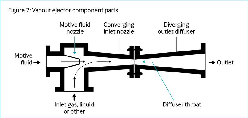
Vapour ejector
The most common system for creating a vacuum is the vapour ejector, which uses a high-pressure motive gas or fluid to entrain a lower pressure stream. Historically, ejectors have been used for a range of vacuum applications from small systems on ancillary plants to very large systems, often with several ejectors in series in refinery vacuum distillation units. Ejectors are also commonly used in upstream applications for flare gas recovery, restart of dead wells and for boosting production (Refer to the Energy efficiency compendium info sheet on ejectors for further details on ejectors).
Condensing ejectors
The pressure of a vacuum column operated at below 20 mmHG can be achieved by using multi-stage high-pressure steam ejectors. Each stage of the ejector will be followed by an interstage cooler. The condensate drains and accumulates into a condensate drum. In the case of a vacuum column operated above 20 mmHg, the use of a pre-condenser (with cooling water as the cooling medium) is often considered in order to minimise the gas rate to the vacuum system and thus limit its energy consumption. The vacuum can be achieved through maintaining or regulating the high-pressure steam or recycle off gas flowing through the ejector system with the pressure controller typically placed at the top of the column.
Ejector system performance at vacuum columns may be independently or concurrently affected by [Reference 3]:
- Vacuum column top temperature and heat balance
- Light Vacuum Gas-Oil (LVGO) pump-around entrainment to the ejector system
- Cooling-water temperature, pressure and flow
- Motive steam pressure
- Non-condensable loading, either air leakage or cracked light-end hydrocarbons
- Condensable hydrocarbons
- Pre-condenser, inter-condenser or after-condenser fouling. Note that fouling impact is typically higher for pre-condensers where there is a very low temperature approach
- Ejector internal erosion or product build-up
- System vent back pressure
Liquid ring vacuum pump
An alternative technology to an ejector is the liquid ring vacuum pump (LRVP), which uses a liquid ring formed in the annular space between the pump casing and the off-centre impeller to compress the gas. This is shown in Figure 3.
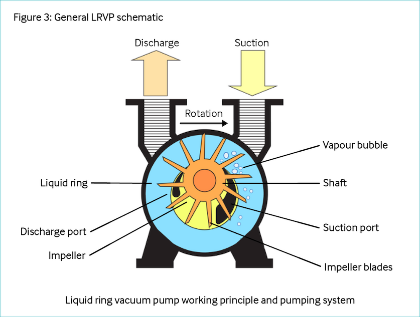
One of the advantages of LRVPs is their ability to discharge at higher than atmospheric pressure. LRVPs can be used on their own or in combination with ejectors. The combined ejector/ LRVP is preferred, with the ejector outlet discharging (after flowing through a condenser) into the suction of the LRVP. API Standard 681, liquid ring compressors and vacuum pumps in petroleum, chemical, and gas industry services covers the minimum requirements for liquid ring compressor and vacuum pump (LRC/ VP) systems for service in the petroleum, chemical and gas industries. The requirements include basic equipment design, materials, fabrication, inspection, testing, and preparation for shipment.
In the vacuum column examples in the previous section, ejectors use vapour (e.g., steam) as the motive fluid, while LRVPs are electro-powered, which can be a consideration for the technology selection. In upstream operations, this technology is generally used for: seawater deaeration at vacuum pressure between 34 and 39 kPa abs. MEG distillation, when reclaiming is required, also uses LRVP to obtain vacuum in the column. A typical pressure is between 15 and 21 kPa abs.
Hybrid systems
Hybrid systems use a combination of an ejector and a LRVP to achieve the desired vacuum conditions and higher efficiencies. The selection depends on the availability of the utilities for the motive fluid for the ejectors.
Technology maturity
| Distillation systems | Vacuum systems | |
| Commercially available | Yes | Yes |
| Offshore viability | Yes (stabilisers) | Yes |
| Brownfield retrofit | Yes | Yes |
| Years of experience in industry | 30+ years | 30+ years |
| Years of experience in oil and gas industry | 30+ years | 30+ years |
Key metrics
| Distillation systems | Vacuum systems | |
Range of application |
|
|
| Efficiency |
|
|
| Energy key performance indicators |
|
|
| Guideline capital costs |
|
|
| Guideline operational costs |
|
|
| GHG reduction potential |
|
|
| Time to perform engineering and installation |
|
|
| Typical scope of work description |
|
|
Decision drivers
| Technical |
Specifically for upstream:
|
Note: consistent steam quality is important for proper ejector performance. |
| Operational |
|
|
| Commercial |
|
|
| Environmental |
|
|
Alternative technologies
The following technologies are currently being developed for improved separation [Reference 4]:
- Hybrid processes (distillation/ membranes/adsorption)
- Centrifugally aided devices
For vacuum systems, the following are technologies that provide similar benefits and may be considered as alternatives to vacuum systems:
- VOC recovery systems
Operational issues/risks
Issues and risks are few and known. The technology has been used for many years for refinery applications.
Operational issues include the following [Reference 5]:
- Fouling of reboilers and condensers
- Plugging, corrosion, or fouling of column internals
- Internal hydraulics, e.g., flooding in column with associated increases in heating and cooling duties
- Internal damage, e.g., tray collapse, etc. or assembly mishaps
- Foaming
- Coking
- Instrument error, i.e., misleading measurement
- Variations of feed
- Controls issues
- Heat integration issues
- Poor packing/tray efficiency
API Recommended practice 572 - inspection practices for pressure vessels highlights the need to inspect fractionation and distillation systems for fouling.
Opportunities/business case
Many distillation designs are available in numerous materials and can be customised for specific applications. The use of process simulation tools and other optimisation tools to optimise the design configurations and heat exchanger networks can be utilised to:
- Improve energy efficiency of plant systems resulting in the reduction of associated fuel usage, GHGs and emissions due to energy recovery
- Increase processing ability (throughput or wider range for feedstock)
Energy efficiency in design
The fractionation column should be designed with a sufficient number of stages/HETP to allow for the efficient separation of products with the required range of feed qualities.
Optimal design considerations for energy efficiency can include the following [Reference 6]:
- Minimum reflux ratio to optimise the amount of energy used for cooling and reflux
- Optimal feed location
- Pre-heating via heat recovery from process
- Heat exchange with pump-arounds or side reboilers (for multiple products)
- Minimum operating pressure to reduce reboiler energy input
When considering a retrofit application, opportunities exist to:
- Improve heat integration and heat recovery
- Improve tray/packing efficiency through improved tray/packing design
- Improve controllability through improvement of control loops which may require additional instrumentations to be introduced
In addition, the entire system should be considered when optimising the utility system, for example, if the reboiler is being heated by hot oil from a heat recovery system versus a fired heater. Another key consideration would be the availability of renewable energy. Where possible, electric heaters and heat exchangers can be considered, depending on the scale of the systems available.
Operations improvements
In operations, the energy efficiency of fractionation columns can be improved via minimisation of the operating pressure which will allow for less energy to be utilised for the separation. A variety of software simulation models and techniques can be used to identify optimal operating points.
Continuous improvements can be achieved through process controls which can stabilise the column operations and minimize the energy requirements of the system. Judicious choice of control set points, along with effective control strategies, can facilitate energy-efficient column operation [References 7, 8, 9].
Industrial case studies
CASE STUDY 1: IMPROPER INTER-CONDENSER DESIGN [Reference 10]
A USA West Coast refinery experienced irregular system performance after replacing an inter-condenser supplied by the ejector system manufacturer with one designed and built by a local heat exchanger fabrication shop. The ejector system vendor sent a service engineer to investigate the issue without being informed about the replacement inter-condenser.
The actual performance of the system differed from the ‘as sold’ system. The first-stage ejector operated in a broken mode, with both suction and discharge pressure remaining unstable. The pressure-drop across the first inter-condenser was excessive, measuring 8.5 mm Hg instead of the expected 3 mm Hg.
The broken first-stage ejector performance and high-pressure drop across the first inter-condenser suggested possible issues such as fouling, cooling water flow rate limitation, high inlet water temperature or excessive hydrocarbon loading.
Before detailing a method to determine the actual cause, the service engineer discussed general performance characteristics with unit operators and discovered that the first inter-condenser had been replaced by another vendor.
The vendor had matched the original unit’s tube count and external dimensions but did not properly design the shell-side baffling to effectively manage hydraulic and thermal requirements.
Vacuum condensers have special shell-side baffling to ensure minimal pressure drop, non-condensable gas cooling, and separation of non-condensable and condensate. It is typical to have different baffle spacing at strategic locations within the shell.
The vendor of the replacement condenser used conventional software to model the performance, resulting in a design with fully baffled flow and consequently high-pressure drop.
In this instance, the high-pressure drop across the inter-condenser caused the system to break performance. The first-stage ejector could not overcome the added pressure drop to reach a discharge pressure where the second-stage ejector would operate.
After removing the replacement unit and installing a properly designed condenser, the system performance returned to satisfactory levels.
CASE STUDY 2: SINOPEC TAHE REFINERY, CHINA [Reference 11]
The existing steam ejector system at the SINOPEC Tahe Refinery in China needed regular maintenance due to corrosion and was difficult to operate due to fluctuations in steam quality and seasonal variations in cooling water temperature. The refinery also wanted to lower energy consumption, reduce GHG emissions and eliminate sour water production. A specialised system, utilising two parallel liquid jet ejector systems, was commissioned. Instead of steam, the liquid ejector system uses the LVGO fraction as the motive fluid. The system produces a 15 mm Hg vacuum at the top of the column and includes a separator, centrifugal pump, and cooler. The minimum direct yearly savings were estimated at USD 226,632 per year (cost basis 2010), as summarised below.
| Parameter | Three-stage steam ejector | Single-stage liquid jet ejector system |
| Vacuum column pressure | 40 mmHg | 40 mmHg |
| Gas flow from vacuum column | 1,150 kg/hr | 1,150 kg/hr |
| Operation time | 8,520 hr/yr | 8,520 hr/yr |
| HP steam consumption | 59,640 tonnes/yr | 0 tonne/yr |
| Cooling water consumption | 3,578,400 m3/yr | 852,000 m3/yr |
| Power consumption | 0 kWh/yr | 8,520,000 kWh/yr |
| Cost of HP stream | USD 656,040/yr | USD 0/yr |
| Cost of cooling water | USD 107,352/yr | USD 25,560/yr |
| Cost of electricity | $0/yr | $511,200/yr |
| Total cost of energy | USD 763,392/yr | USD 536,760/yr |
References
1. Kooijman, H.A., and Sorensen, E. 2022.
6. Kooijman, H.A., and Sorensen, E. 2022.