Passive technology for VOC recovery
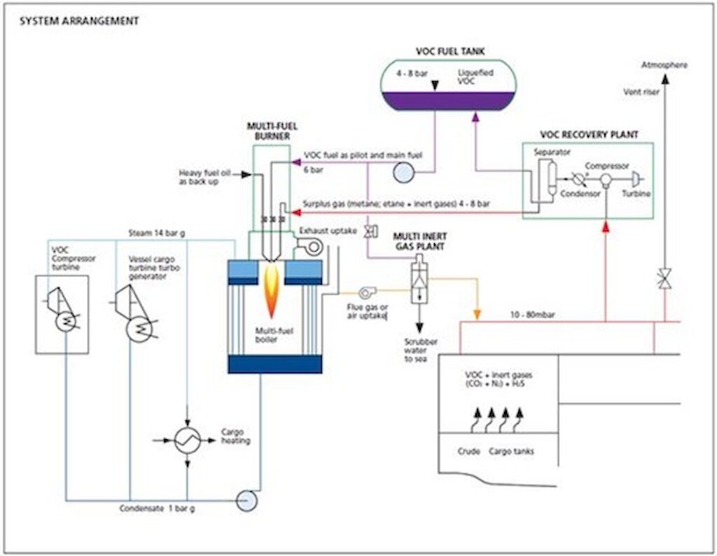
Active technologies tend to be large, complicated and costly to install and operate. Passive technology solutions have therefore been developed as an alternative to active technology.
KVOC technology
One such passive technology is the KVOC® system, developed by Knutsen OAS Shipping AS. The KVOC® technology can be used to reduce the nmVOC emissions that evaporate from loading of the crude oil. One of the key features of this technology is a new drop line design that prevents the flashing generated by the conventional drop line since the pressure is kept at the oil’s true vapour pressure or higher during the entire loading period. This technology is simple and significantly less expensive to install than active technologies. No operational mitigation measures or costs are required. Passive VOC recovery can reduce emissions of nmVOC by 50%, with an operational regularity of 100%. No energy demand is required to operate the passive VOC recovery plants, hence emissions of CO2, NOX and SOX for power generation can be avoided. Operational safety is the same as for ships without VOC recovery units. Other passive technologies include vapour balanced loading and the use of nmVOCs as a blanket gas for storage tanks. Compared to active technology, passive technology is simpler and has much lower emissions related to construction and installation.
Technology maturity
| Commercially available?: | Yes |
| Offshore viability: | Yes |
| Brownfield retrofit?: | Yes |
| Years experience in the industry: | 5-10 |
Key metrics
| Range of application: | Active: Shuttle tankers, FPSOs, FSOs, oil terminals, onshore production sites. Passive: Shuttle tankers, FPSOs, FSOs |
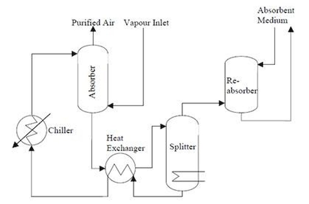
| Efficiency: | Active VOC recovery: Shuttle tankers: 80% (absorption); 90% (adsorption); 100% (condensation with vapour boiler). Storage ships: (FPSO, FSO): 90–100%. Efficiency at Mongstad terminal is >80% |
| Guideline capital costs: | Capital costs for 1 plant (Active VOC Recovery) |
| Guideline operational costs: | Active VOC recovery: Yearly for recovery plant for shuttle tankers (Norway): US$ 1.5 million. Yearly for VRU (United States): US$ 8–17 thousand |
| Typical scope of work description: | Economic analysis and continued technology assessment |
Decision drivers
| Technical: | Footprint: Size, weight, area required, type of crude oil |
| Operational: | Active: Operational complexity
Passive: Easy to operate |
| Commercial: | Crude oil price
Higher amounts of oil to sell due to recovered volatile compounds |
| Environmental: | Reduce greenhouse gas (GHG) footprint
Reduce VOC emissions; VOC near shore may have local environmental effects |
Operational issues/risks
Active system operational issues: Active technologies are complicated and can be challenging to operate properly. Operational regularity for three absorption systems in the Norwegian VOC industry cooperative (VOCIC) was 96%; for eight condensation systems, operational regularity was 92% in 2011.
Active system risks: Safety challenges vary according to the technology implemented. Condensation with boiler control presents risks associated with the storage of VOC, and an additional ignition source. Chilled liquid absorption has the risks associated with the recovery of the absorbent through distillation, and the storage of methanol for antifreeze. Adsorption of hydrocarbons onto activated carbon is exothermic and can lead to hot spots and fires in the carbon bed if not properly managed.
Passive system operational issues: Operation of KVOC® systems is similar to conventional drop lines.
Passive system risks: Safety risks are similar to those on ships without KVOC® systems.
Opportunities/business case
Opportunities:
- Increased amount of crude oil to market
- Recovered vapour
Industry case studies
Active VOC recovery: offshore loading, Norwegian Continental Shelf (Reference 1)
In 2011, 18 facilities (both passive and active) were operating under the VOC industry cooperative (VOCIC) to reduce nmVOC emissions. The cost of nmVOC reductions for VOCIC facilities was about 200 million NOK in 2011. Of this total cost, about 125 million NOK was for capital investment while the remaining 75 million NOK was for net operating expenses. Some VOCIC shuttle tankers use active VOC recovery systems to achieve nmVOC reductions. The table below summarizes the reductions achieved by each ship.
| Ship | Loaded volume (mill Sm3) | Number of loads | System (design reduction efficiency) | Achieved regularity | nmVOC reduction (tonne) |
| Grena | 3,667 | 27 | Condensation (100%) | 97% | 3,366 |
| Karen Knutsen | 4,408 | 33 | Absorption (80%) | 100% | 4,469 |
| Navion Anglia | 1,235 | 11 | Absorption (80%) | 96% | 826 |
| Navion Brittania | 2,094 | 17 | Condensation (100%) | 95% | 2,025 |
| Navon Hispania | 3,555 | 28 | Condensation (100%) | 99% | 3,910 |
| Navion Oceania | 4,081 | 33 | Absorption (80%) | 93% | 3,601 |
| Navion Scandia | 3,292 | 28 | Condensation (100%) | 86% | 3,127 |
| Stena Alexita | 2,285 | 25 | Condensation (100%) | 75% | 2,024 |
| Stena Natalita | 1,137 | 21 | Condensation (100%) | 95% | 935 |
Table 1: Achieved nmVOC reduction by Norwegian shuttle tankers using active VOC recovery systems
(Based on Tables 1 and 5 from Reference 1)
Passive VOC recovery offshore loading, Norwegian Continental Shelf (Ref. 1)
In 2011, 18 facilities (both passive and active) were operating under VOC industry cooperative (VOCIC) to reduce nmVOC emissions. The cost of nmVOC reductions for VOCIC facilities was about 200 million NOK in 2011. Of this total cost, about 125 million NOK was for capital investment while the remaining 75 million NOK was for net operating expenses. Typical unit abatement cost for vapour balancing on tankers and loading facilities is estimated at 40–300 ECU per tonne VOC (Reference 7). Some VOCIC shuttle tankers use passive VOC recovery systems to achieve nmVOC reductions. The table below summarizes the reductions achieved by each ship.
| Ship | Loaded volume (mill Sm3) | Number of loads | System (design reduction efficiency) | Achieved regularity | nmVOC reduction (tonne) |
| Amundsen Spirit | 2,028 | 25 | KVOC (50%)[1] | 100% | 962 |
| Betty Knutsen | 25 | 1 | KVOC (50%)[1] | 100% | 16 |
| Bodil Knutsen | 2,336 | 17 | KVOC (50%)[1] | 100% | 1,361 |
| Elisabeth Knutsen | 3,439 | 28 | KVOC (50%)[1] | 100% | 2,157 |
| Hanne Knutsen | 397 | 3 | KVOC (50%)[1] | 100% | 184 |
| Nansen Spirit | 1,890 | 22 | KVOC (50%)[1] | 100% | 767 |
| navion Norvegia | 2,604 | 20 | KVOC (50%)[1] | 100% | 1,810 |
| Peary Spirit | 326 | 3 | KVOC (50%)[1] | 100% | 181 |
| Sallie Knutsen | 3,871 | 31 | KVOC (50%)[1] | 100% | 2,108 |
| Siri Knutsen | 53 | 2 | KVOC (50%)[1] | 100% | 34 |
| Vigdis Knutsen | 508 | 4 | KVOC (50%)[1] | 100% | 493 |
Table 2: Achieved nmVOC reduction by Norwegian shuttle tankers using passive VOC recovery systems
(Based on Tables 1 and 5 from Reference 1)
References:
- Norwegian Petroleum Directorate (NPD) (2011). ‘Miljøteknologirapporten’ (Environmental technology report). Published March 2011, Norwegian version only.
- Knutsen OAS Shipping AS (website).
- Equinor (website): ‘The Mongstad facility’ (Norway).
- Equinor (website): ‘Sture oil terminal’, (Norway).
- Hamworthy Gas Systems AS (2008). ‘VOC Recovery and Power Generating System: Gas Systems. Ref: HGS 3017 1208/2.
- Shipley, S. (2011). Developing an effective crude oil vapor recovery system. In ‘Port Technology International’, Edition 49, pp 80–82.
- Klimont, Z., Amann, M. and Cofala, J. (2000). ‘Estimating Costs for Controlling Emissions of Volatile Organic Compounds (VOC) from Stationary Sources in Europe’. IIASA Interim Report IR-00-051.
- Rudd, H.J and Hill, N.A. (2001). ‘Measures to Reduce Emissions of VOCs during Loading and Unloading of Ships in the EU’. Report no. AEAT/ENV/R/0469 Issue 2. Produced for the European Commission DG Environment.
- U.S. EPA (2006). ‘Lessons Learned from Natural Gas STAR Partners: Installing Vapor Recovery Units on Storage Tanks’. United States Environmental Protection Agency, October 2006.
- Hartveit, B.E. (2010). Hamworthy Presentation on VOC and FGR recovery: Technology Briefing BG Group, 15 June 2010.


