Topic last reviewed: November 2022
Sectors: Downstream, Midstream, Upstream
Category: Efficient use of power – compressors/drivers
Compressors are an integral part of the production process; they are used to increase the line pressure of the gathering system so that gas can be delivered to processing plants and/or sales lines.
Gas compression is one of the most energy-intensive production processes in upstream operations. For this reason, it is important to investigate the most efficient and appropriate options
Compressor types
Many types of compressors are available, and each of them has its advantages and limitations. The main types of compressors are:
- Centrifugal
- Impellers increase the velocity of the fluid and turn this kinetic energy into enthalpy, thereby increasing the pressure of the fluid
- Limited wearing parts, hence less maintenance intensive than reciprocating compressors
- Axial
- Alternates rotating blades and stationary vanes to progressively compress the fluid across each compressor stage
- Only used for very high flow rates and mainly for air applications
- Reciprocating
- Positive displacement compressors using pistons in cylinders driven by a crankshaft
- Generates a pulsating flow
- More wearing parts, hence more maintenance intensive than centrifugal compressors
- Screw
- Positive displacement compressors using rotating helical screws to compress the gas into a smaller space, hence gradually increasing the gas pressure as the volume decreases
- Two types: oil-flooded (wet) and oil-free (dry)
- Liquid ring:
- Uses a ‘liquid ring’ generated by an eccentrically mounted impeller with the process gas compressed in the spaces between the impeller blades and the liquid ring
Compressor selection
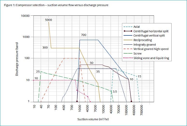
Selection of compressor type by suction flow rate is generally as per Figure 1.
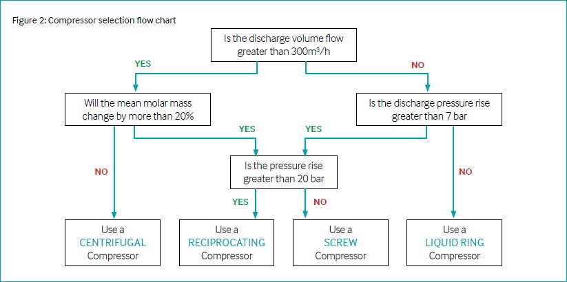
An indicative example of a selection flow chart is shown in Figure 2.
Compressor driver type and selection
Many types of compressor drivers are available, and each of them has its advantages and limitations. The main types of compressor drivers are:
- Electric motor
- Two types: induction and synchronous (for larger powers)
- Can be applied with an adjustable speed device (e.g., variablefrequency drive, VFD, or hydraulic variable-speed drive), where compressor speed control is desirable or necessary
- Minimal maintenance compared with other drivers such as gas turbines
- Steam turbine
- Uses steam to turn a rotor fitted with alternating rotating blades and stationary vanes that drive the load
- Often seen on refineries where steam systems are available
- Gas turbine
- Air is compressed in the axial compressor section of the engine and fuel introduced and ignited in the combustors, and combustion products go through the gas generator and power turbine sections, driving, respectively, the axial compressor and the load
- Gas turbines can be industrial (light industrial or heavy-duty) or aeroderivative, although the distinction between these two types is becoming increasingly blurred
- Multi-shaft arrangements with a free power turbine are typically more efficient at partial load than single-shaft gas turbines
- Gas engine
- Reciprocating engine
- Often paired with reciprocating compressors in field gas applications
Electric motors provide advantages where electric power is readily available. However, the choice of driver is also influenced by the size of the compressor and the power available as well as operability and maintenance requirements.
Compression system
A compression system includes not only the compressor and driver but also a number of subsystems:
- Coolers suction coolers (if present) and intercoolers
- Cooling at suction side of each process stage minimizes absorbed power
- Scrubbers
- To prevent liquids from entering the compressor
- Suction and discharge vessels (if required)
- Pulsation suppression dampeners (for reciprocating and screw compressors)
- Interconnecting piping
- Process control systems
- Recycle (bypass) lines
- Anti-surge systems (axial and centrifugal compressors)
- Instrumentation
- Condition monitoring systems
- Auxiliary systems, such as sealing and oil systems
An indicative compression system is shown in Figure 3. Note that the antisurge lines only apply to centrifugal compressor systems. A cooler is not always present at the suction of a compression system but having the suction stream as cold as possible minimizes absorbed power.
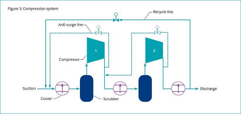
For a positive displacement compressor (reciprocating or screw) a ‘stage’ of compression is from when the gas enters and exits the compressor either to the process or for cooling and readmittance to the compressor. However, for a centrifugal compressor, a ‘stage’ is an impeller and return channel, and a ‘section’ or ‘process stage’ can consist of a number of stages before the gas exits the compressor. Figure 3 illustrates two process stages of compression.
The number of process stages is a compromise – an increased number of stages with intercooling minimizes absorbed power but increases equipment and piping, cost, and complexity. Piping, coolers, and the scrubbers are selected and arranged in such a manner as to minimize frictional pressure drop.
The number of compressors to be applied in a system is, again, a compromise because ‘one large compressor’ will usually be more efficient than two smaller compressors. However, for an operating case of 50% flow rate, the ‘one large compressor’ selection will likely operate inefficiently at half load, while for the ‘two smaller compressors’ selection, one compressor can be switched off and the remaining compressor can operate efficiently at full load. The most appropriate selection can be exercised following to sparing philosophy and operating capacities are identified. Uncertainties associated to expected operating conditions are covered by design margins (oversizing) that may affect efficiency.
For exploration and production applications in which the field is expected to decline over time, it is common to see modification projects where equipment is altered (e.g. redesign of compressor internals) or removed to allow the compression system to operate as efficiently as possible in order to minimize emissions.
Compressor capacity control
Speed variation is the most efficient method for compressor capacity control.
Compressors driven by gas turbines, steam turbines, or gas engines are suitable for capacity control by speed variation due to the variable-speed nature of these drivers.
For compressors driven by fixed-speed electric motors, the simplest method of capacity control is to recycle gas from the discharge of the compression system back to the suction, but this is highly inefficient. There are several capacity control methods that are more efficient.
For centrifugal axial compressors:
- Suction throttle valve
- Common for centrifugal compressors
- Typical method of capacity control in fixed-speed applications
- Inlet guide vanes (axial/centrifugal)
- Common for axial compressors and some centrifugal compressor arrangements
- Situated at the inlet to the first stage and guide flow, adding swirl
- Adjustable speed drives
- VFD adjusts the frequency of the electricity supply to the motor and consequentially the speed and therefore capacity
- Need to ensure that required discharge pressure can be attained at the lowest planned speed
- Hydraulic variable-speed drive in conjunction with a fixed-speed motor can also be used to adjust the speed
- Suction throttle valve
For positive displacement compressors:
- Speed control
- Common method of speed control for reciprocating compressors driven by engines
- VFDs can be used with reciprocating compressors as long as the torque requirements of the compressor can still be met
- Clearance volume
- Used with reciprocating compressors
- Utilizes clearance pockets at the end of the cylinder
- Suction valve unloading
- Used with reciprocating compressors
- Valve held open such that gas enters the cylinder but is not compressed
- Slide valve
- Used with screw compressors
- Alters the length of the compression chamber and consequentially the capacity
- Speed control
Technology maturity
| Commercially available | Yes |
| Offshore viability | Yes |
| Brownfield retrofit | Yes |
| Years of experience in industry | 30+ |
| Years of experience in oil and gas industry | 30+ |
Key metrics
| Range of application | Refer to Figure 1 |
| Efficiency | Typically ranges from 70% to in excess of 90% but highly dependent on application such as distance of operating point from best efficiency point |
| Energy key performance indicators | Efficiency, % recycle (minimize), pressure ratio (minimize), deviation from best efficiency point |
| Guideline capital costs | Dependent on application |
| Guideline operational costs | Dependent on application |
| Typical scope of work description | Driver and compressor, skid or foundation, and auxiliary systems required for operation (e.g., filters, coolers, instruments, valves, lube oil system, pulsation bottles for reciprocating compressors, seal gas system for centrifugal compressors) |
Decision drivers
| Technical: | Process duty, anticipated operating envelope, assessment of available utilities to determine drive type Electrification (i.e.,use electric motors instead of gas-fuelled drivers) reduce GHG emission if the power source has lower emission factor Steam turbines with motors will reduce emissions if the power source has lower emissions, e.g., carbon capture and storage, hydrogen, wind, hydro-electric etc. |
| Operational: | Capacity control method |
| Commercial: | Sparing philosophy |
| Environmental: | Improving efficiency of existing compressors |
| Economic rule of thumb: | Consider total cost of ownership |
Alternative technologies
Ejectors can be applied for certain low-pressure (LP) applications where there is a compatible high-pressure (HP) motive stream.
Operational issues/risks
- Unexpected changes to the process duty (composition, flow rate, pressures, etc.) can cause equipment malfunction
- Severe damage can be experienced when axial/centrifugal compressors operate below (or close to) their minimum operating flow (compressor surge)
- At high flow capacities, centrifugal compressors are limited by the sudden drop of discharge pressure (compressor stonewall)
- Seal systems require constant vigilance to avoid process containment issues
- Driver maintenance (particularly for gas turbine drivers) may reduce the availability of the compressor
Opportunities/business case
Opportunities
- Opportunities to fit existing equipment with adjustable speed drives
- Opportunities to fit magnetic bearings and replace lube oil system for centrifugal compressors
- Trend in centrifugal compressors to develop ‘high head’ impellers to increase compressor capability
- Replacement of a gas turbine with electric motor (refer to case study 3)
- Modified valve designs for reciprocating compressors to minimize losses
- Potential application of ‘single screw’ compressor designs
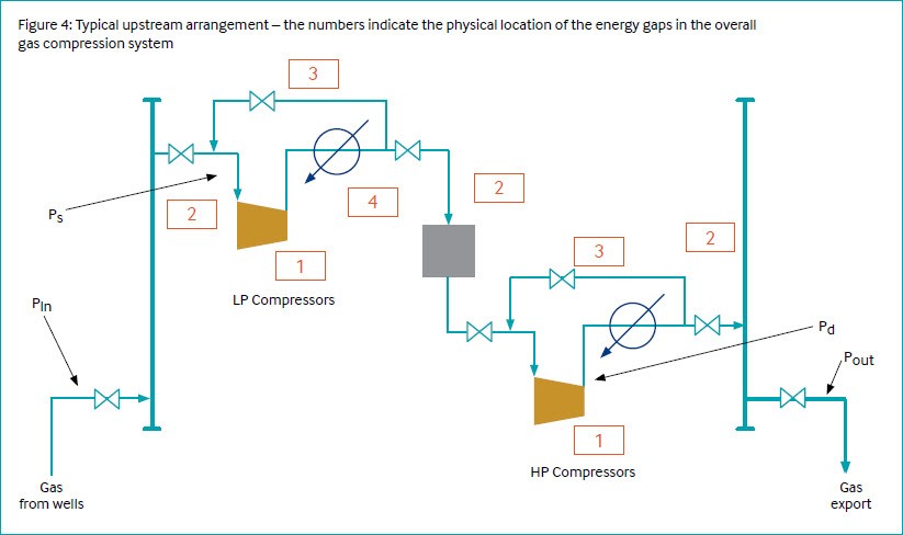
Gas from the wells enters the inlet manifold on the left and passes through an LP compressor to a treatment or conditioning process at intermediate pressure (e.g., dehydration, acid gas removal, dew pointing, or simply no treatment process at all). Then the (treated) gas at intermediate pressure passes through an HP compressor via the export manifold at the right into the export line to its destination.
Over time, the inlet pressure at the inlet manifold (pin) will gradually reduce due to well depletion. The outlet pressure at the outlet manifold (pout) is determined by the receiving pressure at the gas destination and the pressure drop through the export line, which can be substantial if the final destination is located far away from the gas production facility. Depending on the required pressure increase (pout − pin) more compression stages may be required in addition to the two compression stages shown in Figure 4.
In offshore applications, and in onshore applications at remote locations, the compressors are driven mostly by gas turbines. In onshore applications closer to domestic areas and electrical infrastructures, compressors driven by electric motors are commonly seen. In both gas production facilities and gas plants the power/fuel demand for gas compression can account for a significant portion of the total power/fuel demand of the facility – up to over 90% of the total.
Hence, the scope of energy-efficiency improvement and associated GHG emission reduction, is driven by energy demand and governed by applicable laws, international standards and guidelines, and the need to address stakeholder expectations. Proper energy management and effort to minimize overall energy demand will benefit from a gap analysis to provide a breakdown of energy use across the system to understand the extent to which energy use is excessive and what interventions would be required to reduce energy use and CO2 emissions.
Referring to Figure 5, the blue 100% bar on the left represents actual fuel demand from the gas turbines. The blue 69% bar on the right represents required net duty to increase the pressure of produced gas from pin to pout. The green intermediate bars are discussed briefly in subsequent sections. The headings that follow refer to the categories in Figure 4, indicating the physical location of the energy gaps in the overall gas compression system.
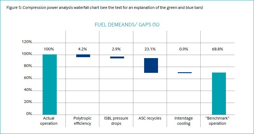
Polytropic efficiency
Analysis of operating data revealed an apparent energy gap of ~4% relative to compressor operation at expected or benchmark polytropic efficiency. Further review will be required by the rotating equipment discipline. Recovery of efficiency to close the gap may require routine maintenance, repair work, or minor compressor modifications. In the event of large structural efficiency gaps, efficiency improvements may require major compressor modifications or even compressor replacement.
Inside battery limit pressure drops
Pressure drop accumulating between the inlet manifold and the outlet manifold requires additional compression over and above the net facility pressure increase (pout − pin). Analysis of operating data revealed that approximately 3% of total fuel demand related to inside battery limit pressure drop – including or resulting from friction loss in block valves and piping systems, pressure drop across control valves, pressure drop across heat exchangers, and equipment in treatment systems – and in-line fouling.
Pressure drop cannot be fully eliminated but may be minimized by a range of interventions, including but not necessarily limited to operational measures to ensure maximum valve opening where possible, modification of control strategies to minimize pressure drop maintained across control valves, modification of equipment, piping system design, flow measurements, etc. to reduce friction losses, and (internal) maintenance cleaning.
Anti-surge control recycling
Anti-surge control system settings may be challenged to minimize recycle valve opening to the minimum required to ensure equipment integrity.
Structural recycle valve opening due to structural overcapacity of compressors during operation may be minimized by compressor modifications (e.g., variable-speed control versus fixedspeed control, if not limited by polytropic head requirements) but may ultimately only be possible by major compressor modifications (e.g., re-bundling) or even compressor replacement. Progressive depletion for this facility has already resulted in a fuel gap of approximately 23% of total fuel demand, associated with maintaining the anti-surge control recycling.
Interstage cooling
In the absence of anti-surge control recycling, deeper cooling of the intermediate pressure gas from the LP compressors to the HP compressors reduces power demand from the HP compressors. Analysis of operating data revealed an apparent energy gap of ~1% of total fuel demand. However, due to continuous recycling, closing this gap will increase the gap from anti-surge control recycling by a similar amount. In the absence of anti-surge control recycling, further review is needed to confirm whether the gap is caused either by fouling or by the outage of the interstage cooler, as the required corrective measures will be different in both of these cases.
Industry case studies
Case Study 1: Compression power analysis
An operator conducted an analysis of compression power as part of a gap analysis for an offshore gas production platform in operation with gas-turbine-driven LP and HP compressors.
In upstream gas production facilities, compressors are commonly used to transfer gas from the wells over long distances in both offshore and onshore gas facilities. Figure 4 shows an indicative arrangement with two compressors in series. In the figure pin is the pressure of the gas from the wells entering the compression system. ps is the pressure at the suction of the first stage compressor, pd is the pressure at the discharge of the final stage compressor, and pout is the pressure entering the gas export system.
Case Study 2: Change gas engines to electric motors [Reference 1]
A North American operator examined the installation of electric motors to replace gas engine drivers and concluded that ‘installing an electric motor in place of a gas-driven engine will increase operational efficiency, reduce maintenance costs, and yield significant methane savings.
Case study 3: Replacement of steam turbines by Electric Motors [Reference 2]
The replacement of a high-speed, steam-driven driver for a compressor provided benefits in terms of higher energy efficiency (assuming electricity from the utility/ grid), less maintenance downtime, and reduced CO2 emissions. The observed improvement in efficiency was from 45% to 50%. The CO2 reduction was approximately 30%. Maintenance of the motor drives will be less frequent as steam turbines require a major overhaul every 10 years compared with 15 years for motors.
During its implementation there were several challenges to be overcome:
- Reliability and maintainability studies of the electrical system
- Driver interchangeability assessment
- Motor integration studies, including torsional analysis and skid design
- Construction and start-up issues
It should be noted that this particular installation experienced a CO2 reduction. The extent of any CO2 reduction (or even whether there is one) is dependent on the generation method of the alternative power source.
References
- US Environmental Protection Agency. “Install electric compressors.” Natural Gas STAR Partners. PRO Fact Sheet No. 103. 2011. https://www.epa.gov/sites/default/files/2016-06/documents/installelectriccompressors.pdf
- Durantay L, et al. “A Success Story of Steam Turbine Replacement by High Speed Electric System Driven Compressor.” PCiC Energy Europe. Paper No. EUR21_08. 2021.