Topic last reviewed: November 2022
Sectors: Downstream, Midstream, Upstream
A cooling system is used to reject heat from a process or plant. Cooling is typically only needed in combination with heating. Many processes, especially fractionation/separation processes, need heat to perform their duty to produce products at specification.
System capacity, and hence system profitability, is determined by its capacity to absorb heat for production purposes. Spent heat needs to be removed from the process. That is why the cooling systems are needed. If cooling systems are bottlenecking, they bottleneck the overall production process and hence overall profitability.
There are many types of cooling systems available that are used in the oil and gas industry. To best optimize the efficiency of a cooling system, a ‘systems approach’ should be used to identify potential savings and performance enhancement. This approach looks at the entire cooling system, including the pumps, motors, fans, nozzles, fill, drift losses, evaporative losses, blowdown, makeup rate, chemicals, flow rates, temperatures, pressure drop, as well as operating and maintenance practices. By focusing on the whole system as opposed to just individual components, the system can be configured to avoid inefficiencies and energy losses. Cooling systems do not operate under one condition all the time and system loads vary according to cyclical demands, environmental conditions, and changes in process requirements.
Cooling systems can use different cooling medium (cooling water, chilled water, refrigerant) and these are discussed later in the Cooling medium section. This Info Sheet primarily pertains to the use of cooling water as it is the most common cooling medium in oil and gas facilities.
To determine whether efficiency gains in a cooling system may be achieved, one should understand the different types of systems and their strengths and shortfalls. In general, all cooling systems will utilize a combination of several of the design features discussed in the next several sections.
Open or closed system
This designates whether the coolant is allowed to contact the environment or not.
Open systems
The process medium is in contact with the environment. Open systems only apply to a wet system but may be a once-through or recirculated design.
- The most common example is a cooling tower where water is cooled by its contact with air. A picture of a crossflow-type cooling tower is shown in Figure 1. The air and water come into contact and heat is exchanged through evaporation. The cooled water is then collected in a basin and returned to the plant.
- Cooling ponds may be used to allow warm water to naturally cool through evaporative loss to the atmosphere. The water in the pond can then be recirculated into the plant as cooling water. Makeup water is required to account for evaporative losses.
- Some systems, such as a wet surface air cooler, combine open and closed design.
Closed systems
The cooling medium is contained within piping and is not in direct contact with air. Heat is exchanged with the process via heat exchangers. Closed-loop systems may be a once-through or recirculated design.
- Heat exchangers of the shell-and-tube or plate-and-frame type
- Air-cooled exchanger: fluid in tubes with air blowing over the tubes for cooling
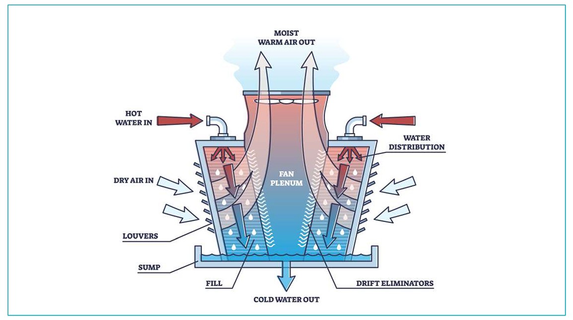
Figure 1: Crossflow-type cooling tower
Once-through or recirculated design
This designates whether the primary coolant is circulated throughout the cooling system multiple times (cycled up) or passes through the system a single time before being discharged (either to its source or another location).
Once-through
In a once-through design the coolant passes through the heat exchanger once before being discharged to another location or returned to its source. For example, water from a river, lake, or ocean may go to the process and then discharge back to the location at a hotter temperature. A once-through system sometimes has an advantage over a cooling tower in that the water source is cooler. There are several potential negatives associated with once-through systems, and these are described in the list below.
- The discharge temperature, flow rate, and impurity limit must fall within permissible limits set by environmental regulation
- System more sensitive to fouling, scale, corrosion, and fish intake
- Risks putting additives into water source
- Once-through water sometimes requires treatment (with both energy and capital costs) before being returned to the environment
- Once-through systems may be challenged as freshwater usage falls under further scrutiny and water reuse increases in priority (although they use less water overall compared with a cooling tower which evaporates a lot of water)
Recirculated
The primary coolant is recirculated throughout the system. In the most common example, cooling water exchanges heat with process users in heat exchangers. The cooling water is routed to a cooling tower, cold water is collected in the cooling tower basin, and the water is then recirculated throughout the plant. Some of the negatives and positives of a recirculated system are in the list below:
- Typically, more expensive than once- through systems due to equipment count (cooling tower, etc.), although it may require wastewater treatment depending on whether chemicals are addeto the water for corrosion, scaling, and microbiological fouling control – if so, there are costs to either create, upsize, or upgrade the wastewater treatment facilities
- Does not have some of the disadvantages of a once-through system in the previous list
- Reduces chance of environmental impact on a water supply (does not eliminate the risk because there is still a blowdown from the tower)
- Does not need as much freshwater due to the recirculation of cooling water, only bringing in makeup water to replace that lost through evaporation, blowdown, drift, and any leaks in the system
- Once-through system will use less water overall if the water is returned to its source
Direct or indirect systems
These are also known as primary and secondary systems. This term indicates whether the primary process medium is discharging heat directly to the environment or to a secondary medium
Direct
A direct system only has a single coolant. For example, the coolant circulates between a heat exchanger(s) and a cooling tower. The process medium is cooled in the heat exchanger.
indirect
An indirect system has two different circuits and can be used to minimize the possibility of process leaks to the environment as well as to potentially lower the cost of equipment for seawater cooling systems (avoids the cost of upgraded metallurgy for all the process heat exchangers). The primary/direct circuit can be a once-through system or a recirculating cooling water system with a cooling tower. The secondary closed-loop exchanges heat with the process units and that heat is exhausted to the primary loop. The efficiency is not as high as in a direct system due to the extra heat exchanger stage. Indirect systems are common in nuclear plants and plants producing hazardous chemicals.
Wet or dry cooling system
A wet or dry cooling system refers to whether cooling water or ambient air is used as the primary cooling medium.
Dry
A dry cooling system uses forced air over tubing with the fluid process medium. Characteristics of a dry cooling system include:
- Only applied to closed systems
- Typical in areas without a cooling water source available
- Tubed fan-coil fin fan coolers – fluid in tubes, air blowing over the tubes for cooling
Wet
In a wet cooling system the process fluid is cooled with air in an open cooling tower or cooled by water in a closed heat exchanger.
- Cooling towers (evaporative heat transfer) including counterflow and crossflow cooling towers and hyperbolic towers – fluid to be cooled is in contact with cooling airflow and there are some evaporative losses
- Shell-and-tube or plate-and-frame heat exchangers
Cooling mediums
Different cooling mediums exist and are discussed in Table 1.
The types of cooling systems chosen may have different environmental impacts although the air and water permits may specify which systems to use. The permits may also specify design features such as maximum permissible withdrawal volume and discharge temperature for once-through systems, cooling tower drift rate, consumptive water use, and noise levels.
A fin fan cooler could reduce a plant’s water consumption, especially in dry locations (although it cannot get the process fluid as cold so does not work in many applications).
When selecting cooling systems, a best available technology (BAT) evaluation should be performed. A BAT evaluation includes an integrated examination of the heat flows within the plant, as improving plant efficiency and reducing heat rejection demands directly reduces the demands on the cooling system. Pinch analysis (see the Pinch Analysis topic) can also reduce the amount of cooling needed.
A BAT evaluation can also look at new technologies to reduce makeup water consumption. A BAT should also evaluate whether the plant can be integrated with other plants to minimize heat rejection. Opportunities in which cooling and heating loads are coupled can have significant efficiency benefits. For example, one can recover heat from a hot production stream by cooling it and using the recovered energy to heat another stream.
Table 1: Cooling mediums
| Cooling medium | Applicable temperature range | Advantages | Major constraints |
|---|---|---|---|
| Cooling water | 32–45°C (depending on wet-bulb temperature and water chemistry) |
|
|
| Air | 50–60°C |
|
|
| Chilled water | 5–12°C |
|
|
| Refrigerant | Below ambient |
|
|
Application of technology
Efficiency gains are available with each cooling system design. New systems have the most potential for optimization, and they can use the latest technology. Existing systems also have the potential to be more energy efficient but are generally limited by layout and construction issues. The type of cooling system selected requires extensive evaluation at the design stage of a project using many design inputs, including costs, layout and size, water availability, energy consumption, energy efficiency, ambient conditions, seasons and weather, minimization of environmental impact, and many others depending on the project.
Annual variations in local water and air temperatures have the largest influence on the efficiency of the cooling system. System efficiency is a function of the costs of the energy and resource input needed to operate the system versus the amount of cooling achieved. Electricity is used to operate fans and pumps, and other costs incurred include makeup water costs as well as regulatory costs and penalties.
Cooling towers
Wet evaporative systems are limited by the wet-bulb air temperature and dry systems are limited by the dry-bulb air temperature. They both fluctuate throughout the year.
The wet-bulb temperature is the temperature read by a thermometer covered in water-soaked (water at ambient temperature) cloth (a wet-bulb thermometer) over which air is passed. At 100% relative humidity, the wet-bulb temperature is equal to the air temperature (dry-bulb temperature). At lower humidity the wet-bulb temperature is lower than the dry-bulb temperature because of evaporative cooling.
Wet-bulb temperature is critical in cooling tower design. It should be measured/calculated at the inlet to the cooling tower. In addition, factors such as recirculation (ingress of the plume from the cooling tower into the air intake) or interference (a similar phenomenon to recirculation except the plume comes from an adjacent cooling tower) artificially increase the wet-bulb temperature at the cooling tower and should be accounted for in design. Improper calculation or estimation of the wet-bulb temperature during design leads to inherent performance issues.
Just like normal heat exchangers, cooling towers also have a minimum approach temperature between the wet-bulb temperature and the cooling water temperature. The Cooling Technology Institute (CTI) specifies a minimum approach temperature of 2.8°C (5°F), and it is very difficult to run lower than this. This limitation may cause a plant to run at reduced capacity or run at lower cooling efficiency at certain times of the year.
If a facility desires more overall cooling (but not a lower approach temperature), additional cooling cells can be added. If the approach temperature is higher than 2.8°C (5°F), the facility should first make sure all its equipment is in working order and check whether the design cooling of the cooling tower has been exceeded.
A common cause of poor performance in cooling towers is degraded and/or fouled fill/packing. Fill can become fouled due to inorganic or organic material, process unit leaks, microbiological growth, etc. Also, fill has a finite life and will start to physically degrade over time. Inspection and replacement of packing should be considered as part of a cooling tower long-term preventative maintenance programme. In some cases, upgrading to a more efficient fill can improve cooling performance; however, the possibility of fouling can increase depending on water quality, so a careful examination should be made before progressing with a design change.
Fans and pumps
Fans, blowers, and pumps may be idled or slowed during times of favourable weather conditions or low plant load to reduce energy consumption. Variable-speed drives (also called adjustable speed drives) are commonly used on fans, blowers, and pump motors because they greatly improve cooling system energy efficiency at partial loads. Some air coolers may be designed such that some fans are fixed and others are variable. Some fans are then shut off or turned on as necessary while the final adjustment (trim) on temperature is done with the variable-speed fan.
The affinity laws suggest that halving the speed of a pump or fan will reduce its energy demand by 7/8ths.
Another example to improve system energy efficiency and reduce ‘balance-of-plant’ loads could be the use of direct-drive motors (e.g., ABB) for fin fan air coolers. This eliminates the need for gearboxes and helps improve reliability.
Automation
Modern controls offer ways to improve efficiency by continuous monitoring of key system parameters with automated adjustments to pumps and fans.
Cooling-medium temperature
The efficiency of cooling systems depends on the temperature of the medium to which the heat is being expelled. Cooler medium are easier to transfer heat to, so less cooling-medium flow is necessary, reducing pumping/blowing energy demands. In many cases, the temperature of water sources is lower than the surrounding air temperature, so using water-based cooling systems can be more energy efficient.
Exchanger approach temperature
As discussed in the Heat Exchangers Info Sheet, the approach temperature is the difference between the cooled working fluid (as it leaves the cooler) and the incoming cooling medium. Water-cooled systems tend to have smaller approach temperatures than air-cooled systems so are preferable in some situations (like product rundown to storage where a colder temperature is needed).
Offshore cooling systems
Cooling systems on offshore facilities often use seawater as the cooling medium, given its plentiful availability and low, steady temperature. Such systems, however, should resist corrosion from this salt water.
Technology maturity
| Commercially available | Yes |
| Offshore and Onshore viability | Yes |
| Brownfield retrofit | Yes |
| Years of experience in industry | 20+ |
| Years of experience in oil and gas industry | 20+ |
Key metrics
| Range of application | Upstream and downstream, liquefied natural gas compression, gas reinjection, gas lift, cooling hydrocarbon gas and lube oil, production, refineries, power stations, and transportation |
| Efficiency | Cooling tower efficiency looks at the approach temperature of the cold water relative to the wet-bulb temperature. If it is the same temperature (impossible), then the efficiency would be 100%. The equation is: μ = (ti − to) 100 / (ti − twb) where
|
| Energy key performance indicators |
|
| Guideline capital costs | Cooling systems can be very expensive for large applications as they have a significant amount of equipment: heat exchangers, cooling tower, controls, connections, controls, inlet and outlet piping, inlet filters, instruments, valves, fans, pumps, tanks, chemicals. There are some modular units for small services, like hospital cooling, that are much cheaper. |
| Guideline operational costs | Operational costs include power for pumps, fans, and controls, costs for water treatment chemicals, and routine maintenance. A cooling tower occasionally needs to be taken offline for maintenance (every 12–-18 years), so there may be lost revenue while it is down. Another option is to rent cooling towers during this maintenance period. |
| Greenhouse gas (GHG) reduction potential | Increasing the efficiency of cooling systems reduces the amount of energy consumed, resulting in a reduction of GHG emissions. |
| Time to perform engineering and installation | 1–24 months |
| Typical scope of work description | Cooling systems are used in a large variety of applications and locations. A typical project will consider the use of cooling systems during initial project planning, determine operating conditions, and evaluate the site conditions, environment, layout, available water, power consumption, operation, and applicable regulations, in addition to energy efficiency before selecting a type of cooling system. After performing a complete system assessment, existing systems with worn or outdated equipment may be improved by looking at new technology that operates more efficiently. |
Decision drivers
| Technical |
|
| Operational |
|
| Environmental |
|
Alternative technologies
There is not really an alternative technology. Decreasing the amount of non-recoverable heat rejected to the environment can allow a plant to reduce its need for cooling systems and increase overall plant energy efficiency. Adding variable flow fans and pumps will allow scalable operation and improve the efficiency of a cooling system.
Operational issues/risks
Cooling systems require regular cleaning, maintenance, and scheduled overhauls to operate at high efficiency. This can range from simple preventative maintenance activities (flushing) to repairs that require the tube bundle to be removed from the heat exchanger shell for cleaning or even replacing entire cooling towers as they age.
Structural integrity can be a concern in cooling towers particularly wood cooling towers as the quality of available wood has decreased over time. Water quality/water treatment is of particular importance to avoid fouling, scaling, corrosion, microbiological growth, as well as deterioration of structural members (both wood and fibre-reinforced plastic).
It is important to treat cooling towers with biocide to avoid microbiological growth not only to prevent fouling but also for industrial health (legionnaires’ disease). Basin cleaning is important as well to avoid pump suction issues but also to avoid Legionella growth in towers. Drift eliminator condition is also quite important to minimize the risk of legionnaires’ disease but also to minimize dri carry-over, which can cause corrosion of adjacent equipment/piping and can also cause issues with outdoor electrical switching stations.
Some cooling systems, such as cooling towers, have a narrow range of operating best efficiency point and may run less efficiently at higher and lower flows versus nominal flow rates.
Study of system flow distribution in consumption side can lead to flow optimization.
In cooling towers fan speed control for a fan can optimize electricity consumption. In some cases one or more fans can be stopped in winter time.
Pumping system can be optimized while adapting to system requirement with variable speed drivers or start/stop philosophy for pumps.
Opportunities/business case
Many cooling system designs are available – some can be customized for specific applications as well as standard designs that are available with minimal lead time at lower costs. Some reasons to upgrade or add cooling systems include:
- To upgrade existing equipment to newer, more efficient designs
- To provide the right sizing of equipment due to initial over or under design
- To provide new systems needed due to regulatory changes, water use, and effluent temperatures
- To reduce energy usage, makeup water, GHGs, and emissions
- To replace existing equipment due to wear and tear, and lower efficiency
- To increase separation and recovery of additional value products (e.g., liquefied petroleum gas, natural gas liquids)
- To provide additional cooling capacity due to an increase in plant output
Industry case study
Cooling Technology Institute (CTI)
The CTI has many papers on best practices and recommended design standards. Many companies around the world use CTI design standards to design their systems.
Automatic disc filter keeps university’s cooling water clean
One university in the United States installed an automatic filtration system on a crossflow cooling tower to remove particulates and control contamination levels. Most cooling towers should have some type of water treatment system to adjust pH and add corrosion inhibitors and antifouling treatments to the cooling water – as well as a water blowdown system. But despite these measures, cooling towers will capture particles from the air which end up in the cooling tower basin and lead to corrosion problems, reduced cooling efficiency, and downtime. Particle build-up creates an opportunity for algae and other biological growth to occur.
An array of disc filters was added to the system to pull water out of the cooling tower basins, filter it, and return it to the system. The system features an automatic back flushing feature to keep filters clean and reduce maintenance. The filter system lowers the plant’s water consumption from basin blowdown and reduces the use of water treatment chemicals. This type of cooling tower is very common to power plant cooling systems and many other applications, and the filtration of basin water is an often overlooked feature in cooling system design. Although the additional equipment adds some new operation and maintenance (O&M) costs, the filter system lowers the risk of reduced heat transfer capacity and reduces maintenance associated with cleaning dirty exchangers, increases plant efficiency for increases and reduces overall cooling system O&M costs.