Topic last reviewed: November 2022

Sectors: Downstream, Midstream, Upstream

Download as PDF

Heat exchangers are used to transfer heat from one medium to another. These media may be a gas, liquid, or a combination of both. The media may be separated by a solid wall to prevent mixing or may be in direct contact. Heat exchangers are required to provide heating and/or cooling to meet a process requirement. Typically, any direct heat input to the system comes from a furnace or steam. Therefore, any inefficiency in the heat transfer at exchangers will require a higher amount of duty from the furnace or steam.

Heat exchangers can also improve a system’s energy efficiency by transferring heat from systems where it is not needed to other systems where it can be usefully used. In general, the heat exchangers are used to exchange heat between two or more process streams or between process stream(s) and a utility stream, which can be either hot or cold utilities.

The selection between using a direct process-to-process heat exchanger versus using utilities to transfer heat depends on the temperature and pressure required by the process stream and whether there is an available process stream to provide that duty given the temperature approach required. When there is no process stream available, a utility stream is required to provide the heating or cooling duty required.

Several examples of heat exchanger applications follow:

  • Waste heat recovery in the exhaust of an electricity-generating gas turbine. Heat can be transferred via a heat exchanger to heat a process stream directly or indirectly via an intermediate heating medium such as water or hot oil. This is the basis for cogeneration. For more information refer to the Combined Heat and Power Info Sheet.
  • Utilizing process heat recovery, which can be optimized via the pinch technique for more complex systems (refer to the Pinch Analysis Info Sheet). A specific example of this would be developing a heat exchanger network to recover the heat from a distillation train to preheat the incoming feed and preheating of crude for water/oil separation.
  • Using a utility, for example water, steam, hot oil, and molten salt, to provide heat duty to a process stream.
  • Using a utility, for example air, cooling water, and refrigerant, to provide cooling duty to a process stream.
  • Selection of the type of hot utility mainly depends on the inlet and outlet target temperatures required by the process stream. Other factors for consideration include the specific heat capacity, cost of the utility, and process safety.

Table 1 provides some common heating media and their relative advantages and disadvantages.

Table 1: Heating media

Heating mediumApplicable temperature rangeAdvantagesMajor constraints
Hot water60–90°C
  • Excellent thermal properties (specific heat, heat transmission coefficient), low viscosity and constant throughout its application range
  • Safe to handle and dispose, not flammable
  • Water quality maintenance requires ongoing intervention and equipment
  • Limited by the process heat temperature required
  • Potential of two-phase flow
Saturated steam100–275°C
  • Temperature of condensation of steam is high, giving a high heat output per mass of utility at constant temperature (compared with other utilities such as hot oil and flue gas that release sensible heat over a broad temperature range)
  • Temperature at which heat is released can be precisely controlled by controlling the pressure of the steam. This enables tight temperature control, which is important in many processes
  • Condensing steam has very high heat transfer coefficients, leading to cheaper exchangers
  • Steam is non-toxic, non-flammable, visible if it leaks externally, and inert to most process fluids
  • Inherent inefficiencies due to boiler blowdown and deaerator losses
  • Inefficiencies can be significant if system is not properly maintained; typical losses in the steam system include losses via steam traps and steam leaks
  • Two-phase flows which can impact pipe integrity
Hot oil180–300°C
  • Hot oil systems can get hotter than steam systems; a single hot oil system can also be more efficient than using several furnaces to provide heat to several services
  • Use of hot oil also reduces the risk of process streams being exposed to high tube-wall temperatures that might be experienced in a fired heater
  • Hot oil systems are often attractive when there is a high pressure differential between the process stream and highpressure (HP) steam and use of steam would entail using thicker tubes
  • Hot oil systems can sometimes be justified on safety grounds if the possibility of steam leakage into the process is very hazardous
  • More equipment and is more complicated than steam
  • Hot oil can loss its properties due to higher temperatures and time
Molten salt400–590°C
  • Higher operating temperatures than synthetic oils (>390°C)
  • Freezing hazard
Flue gas or hot air750–1100°C
  • Flue gas is a waste stream in this example
  • Increases the thermal efficiency of the boiler by reducing the useful heat lost in the flue gas
  • Heat recovery best approach to capturing waste heat
  • Lowers the cost and consumption of heat
  • Low maintenance
  • Improves emission rate
  • Risk of condensing sulphuric acid due to heat removal of flue gas in a heat exchanger; acid deposition leads to corrosion of affected surfaces and fouling and plugging of the heat transfer passages
  • Managing risk may include improved metallurgy / higher cost materials

Table 2: Common cooling-media applications

Cooling mediumOperating rangeTemperature range applicability relative to ambient air
Chilled water5–12°CBelow ambient
Cooling water32–60°CAmbient–100°C
AirAtmospheric temperature>60°C

The two most common cooling utilities (above ambient temperature) are cooling water and air. Refer to the Cooling Systems Info Sheet for more information. Table 2 provides the cooling media that are commonly used and their operating ranges as a guideline for the selection of cooling medium.

The fluids within heat exchangers typically flow rapidly to facilitate the transfer of heat through forced convection. This rapid flow results in pressure losses in the fluids. The efficiency of heat exchangers refers to how well they transfer heat relative to the pressure loss they incur. Modern heat exchanger technology minimizes pressure losses while maximizing heat transfer and meeting other design goals like withstanding high fluid pressures, resisting fouling and corrosion, and allowing cleaning and repairs.

To utilize heat exchangers efficiently in a multi-process facility, heat flows should be considered at a systems level, for example via pinch analysis (refer to the Pinch Analysis Info Sheet for further information). Special software exists to facilitate this type of analysis and to identify and avoid situations likely to exacerbate heat exchanger fouling.

Application of technology

Heat exchangers are available in many types of construction, each with its advantages and limitations. The main heat exchanger types with their relative advantages and disadvantages are provided in Table 3 [Reference 2]. These heat exchanger types have been applied in the industry.

Table 3: Comparison of different heat exchanger types

Heat exchanger typeDescriptionAdvantagesDisadvantages
Pipe-in-pipeEquipment consists of two pipes with different diameters inserted one into the other.
  • Can withstand high flow rate of coolant through selection of pipe diameter, which allows medium to freely flow inside the pipes
  • Ease of maintenance: configuration allows for regular cleaning
  • Versatility: can be used for coolant in both liquid and vapour phase
  • Dimensions: generally larger in size, hence providing challenges in transportation and plot space required for the device
  • High cost: the price of external pipes that are not involved in heat exchange and which are connected to the heat exchanger can be significant
  • Difficulties in the design: use of specialized designers and contractors increases the overall cost of manufacturing and installation
Shell-and-tubeThe most common heat exchanger design type consists of a parallel arrangement of tubes in a shell. One fluid flows through the tubes and the other fluid flows through the shell over the tubes. Heat exchangers are generally specified by their Tubular Exchanger Manufacturers Association (TEMA) type. Tubes may be arranged in the shell to allow for parallel flow, counterflow, crossflow, or both. Heat exchangers may also be described as having tube layouts in single-pass, multipass, or U-tube arrangements. The exchanger may have one or two heads on the shell and multiple inlet, outlet, vent, and drain nozzles.
  • Reliability – more resistant to scale formation
  • Potential for same shell to be used and duty improved by changing internals
  • Long service life
  • High efficiency but less efficient compared with plate-and-frame
  • Can withstand high operating pressures due to its tubular construction
  • Dimensions: generally large
  • Plot space: double the space needed for cleaning (i.e. to pull out the bundle)
  • Maintainability: difficult to clean shell side
  • Potential for metal corrosion due to vulnerability of the outer part of the case as a result of the manufacturing method
Plate-and-frameThin parallel plates are stacked together to create broad, parallel channels. The hot and cold fluids flow through alternating channels. The plates are separated with a gasket or by welding and may have patterns to promote turbulent flow. The plates are stacked together and additional plates may be added on gasket designs to increase heating capacity. The flow may be arranged either parallel or counterflow. The large surface area afforded by the plates means that plateand- frame heat exchangers can allow more heat transfer between the two fluids for a given volume relative to shell-and-tube heat exchangers.
  • High efficiency: due to the large area of the heat exchange surface, the efficiency reaches 95%, which is much higher than that of tubular apparatuses
  • Compactness: smaller footprint for a given duty; however, due to the arrangement of the plates, the size can be significant for higher duties
  • Potential for a single plate to be replaced instead of the entire system, which reduces the maintenance cost or cost of replacement
  • More susceptible to leaks – potential leak causes include high-temperature transients, pressure transients, gasket material compatibility with process fluids, and improper assembly
  • Not recommended for highly fouled service
Spiral-plateMade of two metal plates that are wound on each other. One stream of process fluid enters the heat exchanger through the centre and flows from the outside, while the second stream enters from the outside and flows inwards. This creates a close-to-natural backflow.
  • Compact
  • Can withstand high pressures
  • Not suitable for high temperature or pressure transients
Printed-circuitPrinted-circuit heat exchangers are composed of chemically etched plates joined by a diffusion bonding process. The resulting block is the core of the equipment that dismisses gaskets or welded joints and enables heat transfer between two or more fluids.
  • Very compact equipment and reduced weight in comparison with a tubular exchanger designed for the same service
  • Different patterns of heat transfer plate channels lead to customized design that fits pressure drop requirements
  • Plate disposition allows counter-current heat transfer
  • Does not withstand highfouling fluids
  • Services with high pressure and temperature fluctuation can induce fatigue failure of the equipment
  • Diffusion bonding process is not possible with carbon steel; material limitation impacts on cost

Other types of heat exchangers for specialized services include plate-fin, spiral-wound, and multi-stream heat exchangers. These are primarily used in systems below ambient temperature to minimize the refrigerant duty to be provided.

The heat exchangers discussed so far all keep both fluids contained separately. Two categories of heat exchanger exist:

  • Open-flow – one fluid is contained and the other fluid is not. Examples include air-cooled heat exchangers, duct coils, or open rack vaporizers.
  • Direct-contact – immiscible media are brought into direct contact with each other. Examples include a cooling tower. Refer to the Cooling Systems Info Sheet] for more information.

The relative advantages and disadvantages of air-cooled heat exchangers are provided in Table 4.

Table 4: Air-cooled heat exchangers

Heat exchanger typeDiagram and short descriptionAdvantagesDisadvantages
Air-cooledAir fin coolers, also known as air-cooled exchangers, are used to cool fluid with ambient air. The fluid to be cooled will be in the tube. Air fin coolers can be classified as forced draft when the tube section is located on the discharge side of the fan and as induced draft when the tube section is located on the suction side of the fan.
  • Does not use water for cooling and avoids challenges of maintaining the cooling water system
  • Does not require supplementary system for support
  • Requires more plot space compared with a cooling water exchanger of the same duty
  • Higher fouling tendency of fins in dirty environments
  • High noise due to fans

A comparison of heat exchanger key parameters is summarized in Table 5.

Table 5: Heat exchanger key parameters

DescriptionShell-and-tubePlate-and-frameSpiral-platePrinted-circuitAir-cooled
EfficiencyModerateHighHighHighModerate
FootprintHigh but not as high as air fin coolerModerateSmallSmallLarge
Range of applicability (temperature, pressure, and transients)HighModerateLowLowModerate
Suitability to be used in fouling serviceYesNoNoNoNo

The following sections highlight specific improvements to the existing heat exchanger design to improve heat transfer.

Specific features for shell-and-tube heat exchangers

Flow-deflecting features are often installed in shell-and-tube heat exchangers to improve the heat transfer between the fluids by creating more turbulent flow of the shell-side fluid and more perpendicular flow across the tubes. Such features should be carefully designed to minimize pressure losses and the formation of ‘dead zones’. Dead zones are regions of slow or stalled fluid flow which can lead to fouling (deposition of solids) in the heat exchanger.

Common flow-deflecting features include:

  • Segmental baffles: staggered perpendicular barriers each blocking a fraction of the shell side, including single-segmental, double-segmental, triple-segmental, and no-tube-inwindow baffles – the choice is based on the desired shell-side pressure drop
  • Disc-and-doughnut baffles: staggered circular and annular barriers force the shell-side flow alternately away and towards the axis of the shell
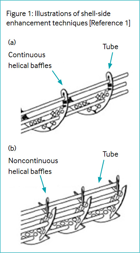
  • Helical baffles: angled to promote a spiralling flow around the shell side. An example of the helical baffle arrangement is shown in Figure 1
  • Rod baffles: grids of rods, usually perpendicular to the shell axis – tubes run axially through the spaces between the rods
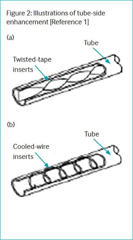
  • Tube inserts: inserts, such as long wire coils, placed inside the tubes to promote turbulent flow and minimize fouling. This is illustrated in Figure 2.
  • Twisted-tube’ design: results in spiralling flow in both the shell-side and tube-side fluids, which can potentially increase the heat transfer with relatively low pressure drops. This is illustrated in Figure 2.

Specific advances for air fin coolers

New air fin cooler designs include:

  • New materials for fan blades that are lighter
  • New configurations of fan blades

Both of these new designs for allow an increase in airflow through the heat exchanger, thus providing more duty to the process to be cooled down for the same heat exchanger footprint.

Additionally, there are new types of fins for an air fin cooler that can increase the heat transfer coefficient and heat transfer area. These include utilization of tube inserts and tube internal diameter enhancements.

Advancements in heat exchangers

Improved heat exchangers typically have higher efficiencies, smaller footprints, and better resistance to corrosion. These can be important especially for retrofit projects.

Another key constraint when deploying these technologies is the cleanliness of the fluid. Due to tighter internal clearances, these may not work with dirtier feeds. The fluid characteristics including potential contaminants should be provided to the vendors for evaluation.

Heat exchanger flow configurations

Heat exchangers have three primary flow configurations:

  • Parallel flow: The two fluids enter at the same end of the heat exchanger and flow in the same direction, parallel to one another. In this design, the temperature differences are large at the inlet, but the fluid temperatures will approach a similar value at the outlets.
  • Counterflow: The two fluids enter at opposite ends of the heat exchanger and flow counter to one another. In this design, the temperature differences are less but are more constant over the length of the exchanger. It is possible that the fluid being heated may leave the exchanger at a higher temperature than the exit temperature of the heating fluid. This is the most efficient design because of the higher temperature differential over the length of the exchanger.
  • Crossflow: The two fluids flow perpendicular to one another.

There can be more than one method of heat transfer in a heat exchanger. Heat transfer will occur using one or more modes of transfer, conduction, convection, or radiation.

Implementation

Proper implementation of heat exchangers in multi-process systems, like oil refineries, requires consideration of the network of heat flows on a systems level. This is often performed through pinch analysis, which matches available heat sources in a system with heat demands, in terms of both the quantity and temperature of the heat. Sophisticated software is available to aid the designer in this process.

Fouling mitigation is also a design consideration and can include various technologies, velocities, bypasses for cleaning individual heat exchangers during operation, and incorporation of spare heat exchangers.

Key considerations when selecting and operating the heat exchangers include:

  • Ensuring minimum velocities are maintained especially over the lifespan of the upstream facility
  • Fouling characteristics and cleaning needs
  • Plot availability
  • Exchanger approach temperature

Heat exchanger fouling

In general, fouling reduces the efficiency of the heat transfer. As the performance degrades over time, more heating duty and associated utilities are required to meet the same heating/cooling demand. This is mapped against the cost of cleaning the heat exchanger to recover the duty. When the cost due to the energy losses outweighs the cost of cleaning, the heat exchanger should be cleaned. Figure 3 provides an example of the curves to identify the optimal time before the heat exchanger should be cleaned.

Figure 3: Cost of cleaning and energy losses as a function of time [Reference 3]

Digital tools can be used to manage heat exchanger fouling. Based on process conditions and component selection, some software packages can predict the rate at which heat exchangers are likely to experience fouling. Software packages are also available to monitor fouling by examining heat exchanger performance over time. Estimates of the costs of cleaning heat exchangers versus the economic benefit from cleaning exchangers (in terms of reduced energy use or more flow through the unit) are also calculated. When the economic benefit of cleaning the exchanger to recover performance because of fouling outweighs the cost of cleaning, the heat exchanger should be scheduled for cleaning when there is an opportunity.

Cleaning of exchangers

Selecting the right method and cleaning medium for cleaning heat exchangers is important to ensure effective cleaning and to avoid damaging exchanger components.

There are three main ways that heat exchangers are cleaned. Each has its own advantages and disadvantages, depending on the process and plant set-up as indicated in Table 6.

Table 6: Cleaning of heat exchangers

Type of cleaningDescriptionAdvantagesDisadvantages
Chemical cleaningChemical fluids are used to remove or dissolve dirt.
  • Able to clean: at industrial scale, calcium deposits, rust, and carbonized oils from the tubes and other cavities with heat exchanger that cannot be effectively cleaned using hydroblasting or mechanical methods
  • Chemicals chosen need to be compatible with material and components of heat exchanger and able to remove or dissolve the foulant
HydroblastingHigh pressure water systems are used to blast away any debris or deposits left in the tubes.
  • Relatively simple as no chemicals are required
  • Safety issue and a need to maintain
    large safety zone when High Pressure water is used
  • Duration of cleaning is lengthy compared with mechanical tube cleaning because water alone is not the best cleaning agent
  • Significant amounts of water needed to clean an exchanger; this may be a limitation for a facility with limited water resources
  • Need to effectively remove water post cleaning
Mechanical cleaningPhysical removal of dirt from tube and services.
  • Mechanical cleaning uses an average of 90% less water than hydroblasting, and this dramatic reduction in water consumption equates to 90% less contaminated wastewater to be contained and treated
  • Compared with hydroblasting and chemical cleaning, heat exchanger can be cleaned faster
  • Limited use due to challenges of removing deposits
  • May not be able to efficiently clean cavities of exchanger

Maintenance of air-cooled heat exchanger

Specifically for an air-cooled heat exchanger, routine checking and maintenance of the blade clearances and the mechanical parts of the air fin coolers can further ensure the air fin cooler performance. For further details refer to Reference 11.

Technology maturity

Commercially availableYes
Offshore viability

Yes

Brownfield retrofit

Yes

Years of experience in industry30+
Years of experience in oil and gas industry30+

Key metrics

Range of applicationAnywhere that a process requires significant heating or cooling that cannot be supplied by heat tracing or ambient conditions.
Efficiency
  • Typical range: 80–95%
  • Efficiency is based on the effectiveness of the heat transfer, i.e. actual heat transfer / theoretical maximum heat transfer
  • The theoretical maximum heat transfer assumes that an approach temperature is not required as the driving force
Energy key performance indicatorsU-factor, approach temperature, fouling resistance, etc. This can be compared with the design as a benchmark.

Additionally, monitoring of the trends is more important than the absolute value to be able to monitor performance degradation.
Guideline capital costsGeneric "rules of thumb" for costs are not applicable due to the wide range of the exchangers available. Costs to consider include the heat exchanger, the skid or foundation, controls, connecting inlet and outlet piping, inlet filters, instruments, valves, fans, pumps, tanks, chemicals, redundancy, as well as installation, start-up, and commissioning expenses.
Guideline operational costs: (to maintain exchangers)Routine maintenance like cleaning of tubes and plates and repairing leaks.
Greenhouse gas (GHG) reduction potentialHeat exchangers can greatly reduce the energy input needs of a process, reducing associated GHG emissions if used for heat integration.
Time to perform engineering and installation1–3 years depending on the number of heat exchangers, complexity of modification, heat exchanger lead time, size and type of heat exchanger, and the window for modification (e.g. turnaround).
Typical scope of work descriptionHeat exchangers are used in a large variety of industries. A typical project will consider the use of heat exchangers during initial project planning, determine operating conditions, and develop equipment specifications. A heat exchanger is generally built by a specialized manufacturer, tested, and delivered to the site ready for installation. Larger exchangers may be shipped in several pieces or even assembled onsite.

Decision drivers

Technical
  • Pressure ranges of the working fluids and the pressure difference between them, and the allowable pressure drop of the fluids across the heat exchanger
  • Temperature ranges for the working fluids and the required approach temperature
  • Properties of the working fluids (physical properties, such as density, viscosity, specific heat, thermal conductivity, temperature)
  • Tendency for the working fluids to cause fouling
  • Flow ranges (turndown) at different operation conditions
  • Availability of cooling medium, e.g. water versus air
  • Space available
  • Governing design codes, including minimum velocity requirements
Specifically for upstream:
  • Minimum velocities over the production profile are to be considered when selecting
    and designing the heat exchanger
Operational
  • System complexity
  • Maintenance needs
  • Level of instrumentation for fouling detection and management / automation for complex exchanger trains
  • Piping for taking exchanger out of service for cleaning without process unit shutdown if fouling is foreseen
Commercial
  • Material selection - Metallurgy (Operations and Maintenance Cost against Capital Expenditure)
  • Delivery time
  • Equipment costs
  • Transportation - Sea lift, stick built, modular, truck/train limitations
  • Parasitic power demands (to run the system)
Environmental
  • Water resources and availability
  • Discharge temperatures
  • Plume abatement
  • Permitting requirements
  • Noise requirements

Alternative technologies

Effective insulation and heat tracing can reduce the heat required if trying to address heat lost to / gained from the environment. Fired heaters or electric heaters are alternatives to adding heat for some applications.

Operational issues/risks

Heat exchangers require regular maintenance to operate at high efficiency and usually require a rigorous overhaul schedule. Much of this effort is aimed at countering the effects of fouling, wherein solids (such as foreign particles or precipitates) accumulate on heat exchanger surfaces, inhibiting heat transfer and restricting fluid flow. Chemical additives can also prevent the precipitation of particles and may be a cost-effective means of fouling prevention.

Overhauls can range from simple preventative maintenance activities (e.g., flushing) to repairs that require the tube bundle to be removed from the heat exchanger shell for cleaning. This downtime should also be taken into consideration when developing the heat exchanger configurations, for example installation of parallel trains that would allow for the heat exchangers to be taken offline for cleaning while the plant is in operation.

Many heat exchangers operate at high pressures and temperatures or with hazardous fluids, and adequate process safety considerations need to be incorporated into the design to avoid personnel risks and system outages.

Heat exchangers are typically regulated by industry codes like those of the American Society of Mechanical Engineers, (ASME), the American Petroleum Institute (API), and Tubular Exchanger Manufacturers Association (TEMA). New equipment designs and any repairs should comply with applicable codes.

Metallurgy is important – it is important that the fluid properties are correctly identified so that, based on the properties, temperature, and pressure, the correct metallurgy can be chosen. Additionally, a proper inspection programme is necessary to make sure that leaks do not develop.

The minimum flow rates should also be considered, especially over the lifetime of the production facility, with varying throughput.

Opportunities/business case

Many heat exchanger designs are available in numerous materials and can be customized for specific applications. There are also standard designs that are available with minimal lead time at lower costs. The key considerations include the condition of the process streams and the available footprint.

Benefits of using heat exchangers include:

  • Energy-efficiency improvements of plant systems due to energy recovery
  • Reduction of associated fuel usage, GHGs, and emissions due to energy recovery
  • Improved safety considerations in ensuring product rundowns and effluent discharge meet required specifications
  • Increased processing ability due to the ability to provide additional heating or cooling capacity requirements

For energy improvement or plant revamps, opportunities exist to replace existing heat exchangers with more efficient and/or more reliable heat exchanger designs.


Industry case studies

Case study 1: Retrofit of industrial heat exchangers with compact heat exchangers

This study highlighted the benefits of swapping heat exchangers from conventional shell-and-tube to plate heat exchangers for a retrofit project. This is because the plate heat exchangers have an overall heat transfer coefficient that is two to three times higher than the conventional shell-and-tube heat exchanger. The study concluded that it was possible to reduce the heat exchanger network from ten shell-and-tube heat exchangers to four plate-and-frame heat exchangers, giving a reduced cost for the retrofit of a preheat train. For further details refer to Reference 4.

Case study 2: Vertical heat exchanger cleaning

A refinery was experiencing cooling issues throughout its entire cooling system. This was due to significant scaling on the shell and tubes of one of its heat exchangers. Shutting the plant down to replace the heat exchanger was not an option, and due to the severity of the situation, the refinery needed a reliable chemical with a history of dissolving scale safely, effectively, and quickly. The cleaning solution selected was circulated throughout the heat exchanger for six hours. The heat exchanger was back to original equipment manufacturer specification with chemical cleaning and the refinery kept operating.

Case study 3: Gas cooler upgrading

A gas storage site was facing cooling capacity issues with its gas coolers, especially during summer when ambient temperatures are extremely high.

Based on the site audit performed it was observed that airflow was found to be 25% lower than design and coolers were designed for a relatively low ambient temperature (30°C versus a maximum of 37°C for this region).

The gas coolers were revamped by upgrading the following parts:

  • Complete fan set
  • New motor and gearbox
  • New fan shaft with top and bottom bearings
  • New anti-rotating device
  • New electrical cabinet

After upgrading the coolers, new site measurements showed that airflow was increased by 35%, the outlet process temperature decreased by 4–5°C, and it was possible to operate the coolers without any issues during the summer.

Case study 4: Replacement of cooler bundles in air fin cooler

The equipment had been performing heavy duties at the site since it was delivered nearly 30 years ago. Replacing the cooler bundles in an air fin cooler at a large onshore gas facility due to wear and tear using more environmentally friendly tubes as replacements offers advantages over conventional technologies. The new tubes provide a higher heat transfer rate with lower emissions and use less power.

References

  1. Smith R., Pan M., Bulatov I, “Heat Transfer Enhancement in Heat Exchanger Networks”, Handbook of Process Integration, Minimisation of Energy and Water Use, Waste and Emissions, Woodhead Publishing Series in Energy, 2013, Pages 966-1037 Heat Transfer Enhancement in Heat Exchanger Networks - ScienceDirect. https://www.sciencedirect.com/science/article/pii/ B9780857095930500320
  2. Edreis E and Petrov A. “Types of heat exchangers in industry, their advantages and disadvantages, and the study of their parameters.” IOP Conf. Series: Materials Science and Engineering 963. 2020. 012027.
  3. Di Pretoro A, D’Iglio F, and Manenti F. “Optimal cleaning cycle scheduling under uncertain conditions: a flexibility analysis on heat exchanger fouling.” Processes 9:1. 2021. p. 93.
  4. Arsenyeva O, Orosz Á, and Friedler F. “Retrofit synthesis of industrial heat exchanger networks with different types of heat exchangers.” Chemical Engineering Transactions 88. 2021.

E-mail alerts

Sign up to receive Ipieca's e-news
Climate
Nature
People
Sustainability
Marine spill
Please confirm that you are happy to receive newsletters from Ipieca: