Topic last reviewed: November 2022 Sectors: Upstream, Downstream
An ejector is used in upstream processing to compress or boost the pressure of an entrained fluid. It is an alternative to a vapour recovery unit (small compressor recovering gas) in some applications. It can be less capital cost, lower operational costs, and less maintenance intensive.
An ejector is not as common as a compressor in upstream processing (especially offshore applications) because it needs a high-pressure motive fluid (gas). This is not available if the site mainly recovers oil. Ejectors are also more complicated to design and use in production fields where new wells are regularly being drilled and wells are continuously changing output over time.
Ejectors are also used in the downstream sector and other industries where vacuum systems occur. Here, they are an alternative to a vacuum pump or liquid ring compressor.
Gas ejectors use high-pressure gas to compress surplus or low-pressure gas, flare gas, or vent gas. They are useful when the gas (and motive gas) can be compressed high enough to get to its destination. If the gas cannot be compressed high enough, it will need recompression and it may be more efficient to instead use a single compressor for all the compression.
Ejectors can also be called eductors or jet pumps, although some only use the term eductors when the motive fluid is a liquid. An ejector is based upon Bernoulli’s principle, which states that when the speed of a fluid increases, its pressure decreases, and vice versa.
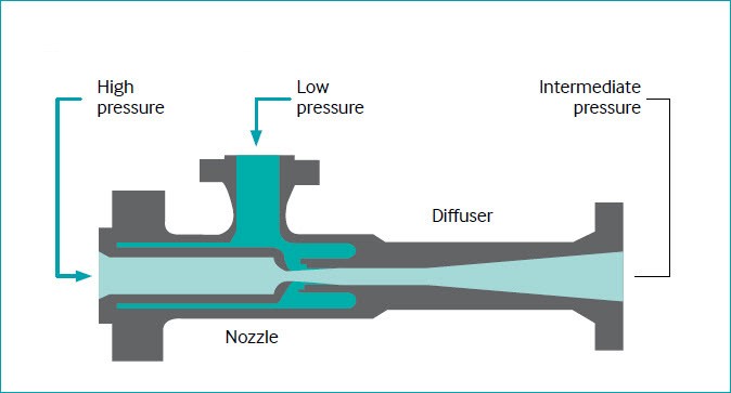
Figure 1 shows the basic components of an ejector designed for use with gas. It has three connection points: one for the high-pressure gas (motive fluid), one for the low-pressure gas, and one for the discharge. The ejector uses a converging nozzle to increase the fluid velocity, which converts the pressure energy of the highpressure fluid into kinetic energy.
Figure 1: Illustration of an ejector
This conversion of static pressure to velocity pressure results in a low-pressure zone at the vena contracta that provides the motive force to entrain a side fluid (or gas). The mixed fluid then flows through a diffuser section comprising a diverging nozzle. This reduces the velocity and increases the pressure, thereby recompressing the mixed fluid. This enables the ejector to discharge at a pressure that is greater than that of the low suction branch.
An important variable in ejectors is the ratio of the motive fluid pressure to the discharge pressure. The larger the ratio, the smaller the amount of motive fluid required. Motive fluid pressure is typically around 5–10 times larger than the discharge pressure.
IOGP Report 647 – Recommended practices for design and operation of flare gas recovery systems has a section on ejectors with additional information.
Ejectors and eductors can be used in a wide variety of applications, and some examples are discussed overleaf.
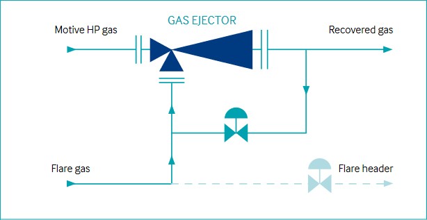
Ejector flare gas recovery system
System designs in which the flare gas is compressed into the fuel gas system are common. An example of an ejector in a flare gas recovery system is shown in Figure 2. The ejector system should be designed to avoid creating a vacuum in the flare gas line to avoid air ingress (flammable mixture) and ensure safe operation.
Benefits
Waste gas recovered and added to production
Reduction in carbon emissions or potential fines for non-upset/ continuous flaring
Figure 2: Illustration of ejector flare gas recovery system.
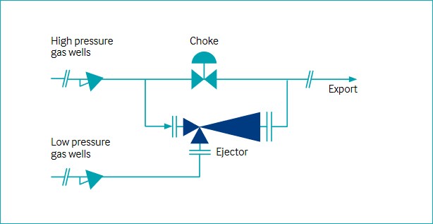
Restart of dead wells
This equipment can be used to restart production of existing low-pressure wells which have been shut in for years due to high backpressure. An example of this is shown in Figure 3. If a suitable high-pressure well is available nearby, the pressure energy that is normally wasted across a choke could be used to drive an ejector to entrain the gas from the low-pressure well.
This can then bring the well back into production, and the need for additional external gas compression is reduced.
Figure 3: Illustration of restart of 'dead' wells ejector application.
Boosting Production
In some cases, an increase in gas production is not possible without adding another compressor. Yet, by using an ejector upstream of a compressor, the manifold pressure of the wells is reduced and thus gas production is boosted. The increase in production can reach up to 15% as a function of well performance.
Benefits
Capital cost, energy, and greenhouse gas (GHG) emissions savings relative to second-stage compression option
Gas ejector much faster to install than second or third stage of compression
Easy replacement of ejector internals to maximize production throughout field life (continual reduction of well pressure)
Gas recovery from storage tanks
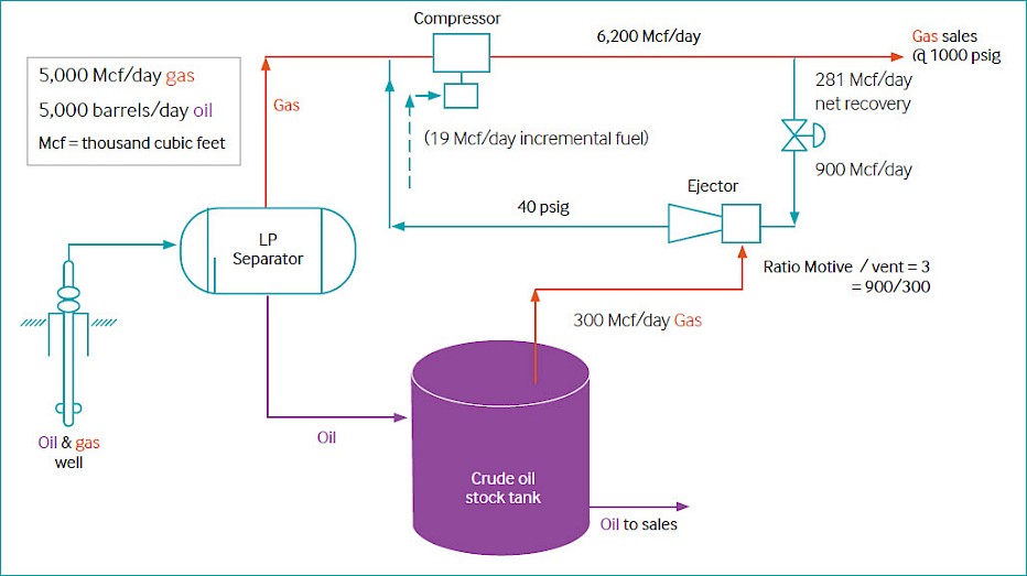
Ejectors can be used to recover gas that currently is flared due to working losses from storage tanks (which occur when tank crude level changes and when crude is agitated) and standing losses (which result from the thermal expansion and contraction of the tank and vapour mixture from the daily heating cycle).
An example of this is shown in Figure 5 (and described more in Reference 1). The ejector system should be designed to avoid creating a vacuum in the storage tank vent line which could cause air ingress and a flammable mixture hazard.
Figure 4: Gas recovery from storage tanks.
Deaeration of seawater
Ejectors can be used offshore on vessels that deaerate seawater. The ejector pulls a vacuum on the vessel containing seawater, which pulls more air out of the water. In this case the motive fluid is typically compressed air which did take energy to compress but is likely already in service at the site.
Refinery: pulling a vacuum on crude unit vacuum column
The most common application of an ejector in downstream processing is on a vacuum distillation column in the crude unit. There are usually several ejectors in series that pull a vacuum, and the motive fluid is steam (not an existing high-pressure motive fluid). The vacuum allows the crude oil to vaporize at a lower temperature. This minimizes the cracking of molecules and reduces furnace firing.
As mentioned at the beginning of this topic, ejectors only work when a high pressure motive fluid is available. In the upstream oil and gas industry, typical ‘motive’ high-pressure fluids are:
High-pressure wells
Recycle gas (spillback) from a compressor
Export oil or gas
Fuel gas (if pressure high enough)
Injection water
Gas or liquid from first or second-stage separator
Gas injection or gas lift
Alternatively, a high-pressure fluid can be generated to be used with an ejector. An example would be the use of a closedloop water system where water is pumped so it can be used as a motive fluid for an ejector. The water is then recovered in a downstream separator and recycled back to the pump.
Technology maturity
Commercially available
Yes
Offshore viability
Yes
Brownfield retrofit
Yes
Years of experience in industry
30+
Years of experience in oil and gas industry
30+
Key metrics
Range of application
There is a large range of applications as discussed at the beginning of the document
Efficiency
N/A
Energy key performance indicators
Uptime or utilization of the ejector, especially in applications where a compressor is run when the ejector is not in service.
In applications trying to maximize vacuum: amount of vacuum (pressure) in vessel compared with design and desired performance.
Minimization of spillback in ejectors that have spillback design (use less motive fluid or shut down an ejector if have several parallel ejectors).
Flow rate of motive fluid (reduce if do not need that much capacity in ejector). If the motive fluid is an existing high-pressure source that is going to be let down across a valve anyway, then a KPI to reduce motive fluid flow rate is not important.
Guideline capital costs
Ejectors are generally cheaper than compressors, but the motive fluid should already exist at a high enough pressure. If compression or pumping is needed for the motive fluid because it does not already exist (like from a well or existing compressor), then adding a compressor or pump would add significant capital expenditure and operating expenditure to the ejector.
Guideline operational costs
Operational costs are significantly lower than those of a compressor as an energy source is not needed. There are no moving parts so an ejector is virtually maintenance- free. In dirtier services, a filter is needed upstream, which will add some capital and maintenance costs.
Typical scope of work description
The ejector design begins with stream properties and conditions in order to design the proper ejector system. Specialty ejector vendors should be consulted.
Decision drivers
Technical
Requires a compatible high-pressure motive fluid
If the application is to work, a gas ejector solution is much faster to put in place than a second stage of compression
Additional limitations of ejectors are discussed in the following section – ‘Alternative technologies’
Operational
See the section ‘Operational issues/risks’
Commercial
Relatively low costs mean project upgrades become cost-effective.
Environmental
Reduced GHG footprint through efficiency / production rate improvements and reduced venting.
High GHG reduction potential when used in flare gas or low-pressure vapour recovery applications.
Alternative technologies
A vapour recovery unit (small compressor recovering gas) is the main alternative technology. It is more common in industry for several reasons:
Some sites do not have a highpressure motive fluid.
The ejector discharge cannot be at a high enough pressure to get into the correct system.
With the change in output from wells over time and the need to regularly drill new wells, it is more complicated to design and use an ejector. Also, the high-pressure motive fluid will need to be occasionally changed. This is even more complicated offshore where you have fewer people available to repipe the motive fluid from one well to another.
Facilities mainly recovering oil instead of gas will not have the high-pressure gas needed as a motive force.
Onshore facilities might be better applications for ejectors because people can more easily make adjustments to the ejectors as motive fluid flows and pressures change. Limitations in people resources are not present to the extent that they are in offshore applications.
Operational issues/risks
Flow rate variability of the low-pressure gas is common. If this variation is not controlled, the suction pressure created by the gas ejector will also vary. To maintain the desired pressure on the low-pressure side of the gas ejector, some standard control techniques are available, including the following:
Recycling of gas from the discharge side of the gas ejector back into the low-pressure side
Incorporation of an integral highpressure gas regulating assembly which varies the motive fluid consumed
Another operational risk is erosion fouling from solids in the gas. Also, at sonic velocities through the venturi throat, there will be wear and tear of the nozzle. Wear and tear increases the motive fluid demand for the same performance. This often goes unnoticed or, if noticed, unactioned. This causes the ejector to operate at ever-increasing motive fluid demand / steam demand and associated increased operating cost.
Therefore, any pre-treatment that might be done for a compressor (such as filtration) should also be done for an ejector.
A safety risk is that the ejector system can create a vacuum in the line and cause air ingress, which leads to a flammable mixture. The ejector system needs to be designed correctly so that this does not occur.
Some troubleshooting tips for ejectors is covered in Table 1 overleaf.
Look downstream for problems that could be: a) an inter-condenser problem b) an ejector problem c) a restriction in the discharge piping d) non-condensible gas load is above the design rating pressure
6
Higher than design suction pressure (assuming motive gas pressure is normal and discharge pressure is equal to or less than design)
6
Greater than design process load or mechanical problems with ejectors—either worn internals or possible internal gas leak around nozzle threads
6a
Inspect internal dimensions and replace if necessary
6b
Tighten nozzle if necessary or seal weldnozzle to motive gas supply line
Opportunities/business case
Low-pressure gas compression (same benefits as adding a compressor)
Increasing gas production
Restarting shut-in wells due to high export pressures
Reducing tendency of wells to load with condensate
Increasing total field recovery
Advantages of ejectors compared with mechanical compressors
No moving parts, hence low maintenance requirement
Low to no running costs if a high-pressure motive fluid exists – ejectors can use high-pressure gas energy traditionally wasted across a choke valve or high-pressure recycled gas from an existing compressor
Relatively low costs mean project upgrades using ejectors become cost-effective
Reduction of energy usage and associated carbon dioxide (CO2) emissions (unless the alternative compressor is electric from a highly renewable electric grid, not diesel/gas driven)
Fast-track installation makes short-term well opportunities viable
Minimal disruption to existing production operations
Low weight and compact size allow installation on most production facilities
Performance can be easily modified to suit depleting well conditions
Ejectors are suitable for both onshore,topside, and subsea installations
Safe, reliable operation
Easy to control using standard techniques
Accidental entrainment of liquid slugs may cause momentary interruption in flow but no damage to equipment
Advantages of mechanical compressors compared with ejectors
No need for a high-pressure motive fluid
Can sometimes support more production
Simpler to design and use in production fields where new wells are regularly being drilled and wells are continuously changing output over time
Industry case studies
Case study 1: North Africa
In this application, an ejector system was installed downstream of a high-pressure separator, as depicted earlier in this document under the heading, ‘“Boosting production’”. There was a low differential pressure between the older wells and the separator. After the installation of the ejector, the oil and gas production from the wells increased, and the ejector paid for itself in a short timeframe.
In the first case study from this paper, gas from wells existed at a pressure of 7-9 bar(g). An ejector was installed at the outlet of the separator for this gas, and the pressure was increased to 10 bar(g). This allowed the gas to bypass the first stage of the compressor, which increased production from the plant (without increasing energy usage).
Case study 2: Offshore example
The case study described here provides an overview of the kind of issues that may occur during ejector implementation.
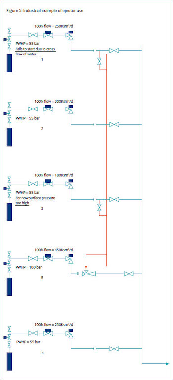
The project is depicted in Figure 5. It consisted of evaluating the benefits of installing an ejector, with Well 5 as motive fluid and Well 1 and Well 3 as entrained fluid. The justifications for an ejector rather than a booster compressor in this case were:
The platform had no power to run an electrical compressor.
It was unmanned so rotating machines were avoided.
A gas- or diesel-driven compressor would have had CO2, sulphur oxides, nitrogen oxides, and particulate emissions and incur the additional costs of fuel consumption.
The ejector was a small device with no moving parts.
The ejector was driven by an existing force (Well 5).
Costs were driven by piping works offshore and associated production losses. One major expectation was the frequent changeout of the ejector internals to cope with the decline in production.
Important remark
The expected behaviour of each of the wells in question was difficult to forecast because:
Well 5 was newly developed with no historical data.
Well 1 stopped producing after four years due to a water crossflow from the bottom reservoir to the top reservoir that took some time to shut off.
Well 3 was killed by too much formation water production after three years.
Implementation of the ejector
The efficiency of an ejector increases with the differential between motive fluid and entrained fluid in terms of flow rate and pressure. For this reason, the project had to be implemented quickly in anticipation of the decline of Well 5. The project was performed within 8 months.
Additional dynamic information from Well 5 was gained. A redesign of the ejector was performed with the additional constraint of respecting the initial equipment footprint.
Results
The ejector was effective in reducing the wellhead pressures of Well 1 and Well 3 as planned but, unfortunately, the 20-bar reduction was insufficient to restart either of the two wells. The ejector was a technical success, but the candidate wells did not respond as expected.
Well 1 was dewatered by means of nitrogen injection, after which it was opened with the ejector and restarted. After six months, the output was three times higher, and production was stable with the well operating on its own.
Subsequently, the ejector was connected to another well on the platform – Well 4 – where it was used successfully to stabilize and increase production. Thanks to the ejector, this previously dead well was restarted successfully.
For Well 1, the costs of the ejector installation and the nitrogen lifting operation were paid back in a short timeframe. The internals of the ejector are changeable, and the main part can be reused in a future project after the decline of Well 5.
Due to the success of this ejector, it has become established as a technology that is investigated systematically for each new project. The installation of an ejector is also a major stepping-stone to other innovative projects such as wellhead compressors (subsea research and development).
References
EPA (2009). ‘Installing Vapor Recovery Units: Lessons Learned from the Natural Gas STAR Program’. Interstate Oil and Gas Compact Commission, Charleston, West Virginia, February 2009. https://www.epa.gov/natural-gas-star-program
“The Ejector Technology in Oued Zar Plant” 2010 SPE Production and Operations Conference and Exhibition