Topic last reviewed: November 2022
Sectors: Downstream, Midstream
Energy-efficient oil and gas processes require less power and heat (natural gas, fuel gas, etc.) and therefore produce less carbon dioxide (CO2).
Energy-efficient designs consider the facility as a single system and aim to minimize overall energy use across the expected range of operating conditions. They involve a comparison of the lifetime energy savings versus incremental costs of different alternatives.
There is a hierarchy of energy-efficient design approaches, where the top level is to select a processing route or technology that consumes less energy in the first place. These then need to be sized correctly and heat integration opportunities and optimization of the utility system studied (including the heat/power ratio as appropriate). Finally, individual equipment can be designed and efficient system components selected (e.g., pumps, compressors, artificial lift, injectors, heaters/boilers, heat exchangers, reactors, distillation columns, piping).
It is much easier to address energy efficiency in design than to retrofit an existing facility to make it more energy efficient. In fact, adding energy efficiency in design may allow a facility to defer other hardware upgrades or retrofits for post-combustion CO2 control (e.g., carbon capture).
Specific challenges unique to upstream processing (versus refining) include varying process flow rates (as fields peak then decline) and a general lack of measurement of energy-influencing variables. Metering is critical to optimization but is often not included in design. Two other concerns deserve closer examination:
Modularity
This refers to a recent trend in upstream processing to design facilities using a factory model approach to save time and money and use the same design for all new developments in a particular field or area. This can be efficient from a design and construction perspective but result in operational inefficiency. For example, a single pump or compressor size is selected even though it may not be optimized for the specific flows of the plant. This factory model approach generally applies to distributed operations rather than large complex upstream facilities such as liquefied natural gas (LNG) plants, sour gas plants, or single large deepwater platforms.
Self-power/heat generation and access to low carbon energy streams
Many upstream sites do not have access to third-party utility grids for electricity and clean pipeline grade gas. As a result, they should generate their own power by using either field gas or diesel. In addition, especially for distributed upstream operations, these fields operate a lot of small, dispersed systems – pumps, compressors, heaters, drilling rigs, etc. Some of these systems use diesel instead of gas due to the lack of a gas distribution network for equipment powering. Being able to supply all these loads with low carbon power over wider geographic distances (both onshore and offshore) may be trickier than for refineries, which are generally onshore and near industrial centres that already have a solid power infrastructure and may have access indirectly to green power and gas via utility grids.
- Inclusion of measurement and control elements of “energy-influencing variables” is critical to optimization in operation.
General design criteria
Considering energy-efficiency alternatives
In designing a new oil and gas facility, there are several ways in which energy efficiency could be considered:
- As part of a minimum required engineering standard based on most recent best practices and/or best available technology. In this case, no additional justification is required.
- As an ‘“enhancement’” to the base design. In this case, the energy- efficiency benefit could be considered with respect to the base case. Calculation of this benefit could look at the overall incremental value added (e.g., incremental net present value, payback, or rate of return) over the life of the project compared with any incremental capital cost. It could include some or all of the following:
- Incremental net energy operating expense (should be negative since energy is saved)
- Incremental non-energy operating expense (includes other factors, such as operations and maintenance, (O&M), which may or may not decrease depending on the case)
- Incremental revenue (e.g., associated gas saved that is then sold)
- Greenhouse gas (GHG) cost reductions (due to energy savings), where CO2 is taxed or will be in the future
- Energy- efficiency rebates and other incentives if applicable
- Incremental or avoided capital expenditure (CAPEX) –: adding energy efficiency will not always increase capex. It could
mean choosing a more efficient motor, pump, compressor, or turbine over another, which may depend on manufacturer
or model type. However, in some cases it will increase capex, such as adding inlet cooling or waste heat recovery to gas turbines. These costs could be offset by:- Cooling, which may allow production of extra power during hot months, which in turn could offset the need for extra power generation capacity
- Waste heat recovery and more extensive use of piping and vessel/tank insulation could avoid the cost of a new boiler
- Lithium-ion batteries could shave peak loads, avoiding over-sizing of electrical equipment
- As a co-benefit for another design alternative that is not added only to save energy. For example, a field decides to centralize production facilities and installs larger (and more efficient) systems (e.g., gas turbines, rotating equipment) This centralization is not being done for the sole purpose of saving energy but does have that benefit. In this case the incremental energy efficiency should be added to the economics as described previously.
If there are other co-benefits, risks, or trade-offs (e.g., reliability versus efficiency, technology risk/readiness, scheduling delay) associated with the more energy- efficient design, these should be highlighted and if possible quantified as well.
Basics
Energy-efficient design criteria should be incorporated into the early phases of a project. In the early phases of greenfield projects, larger changes can be integrated into the design to make it more energy efficient with minor impact on project costs and schedule. Energy-efficiency gains from upgrading existing facilities, however, can be constrained by the arrangement of existing equipment and available plot space.
As a project progresses, all decisions that affect energy efficiency should be documented, including what assumptions went into that decision. This will begin in the pre-feasibility study and continue through detailed engineering and will often involve both a technical and economic component. Identifying these energy-efficiency opportunities is useful as some will be further investigated and matured in later project phases.
Benchmarking projected energy usage with similar projects is important. However, in upstream fields it is important that proper benchmarks are identified as the processes are different from location to location due to different characteristics of the fluids, reservoir formations, and geography.
The overall design of the facility should include the necessary instrumentation and associated hardware to allow for monitoring and optimization of the system. This is important for the energy management system in a commissioned facility.
The instruments should be able to measure energy flows (fuel gas heating value and flow rates, power/electricity consumption, reactive energy, etc.) being used by the large energy consumers (e.g., gas turbines) as well as monitor equipment performance and help it operate efficiently by monitoring energy key performance indicators (KPIs). More information on energy KPIs can be found in the Energy Performance Monitoring and Optimization Info Sheet.
For continuous monitoring, these instruments are to be linked to a data historian and plant information system. This allows detailed analysis to be conducted when needed.
Appropriate process control, including advanced process control, should also be incorporated in the energy-efficiency design. This is described in more detail in the Energy Performance Monitoring and Optimization Info Sheet.
Upstream facilities design
The upstream oil and gas business is different than refining in that the output of an upstream plant is typically not constant during its life. As depicted in Figure 1, it is instead usually characterized by an initial ramp-up phase with increasing rates, a plateau phase with a constant rate, and a depletion phase with decreasing rates.
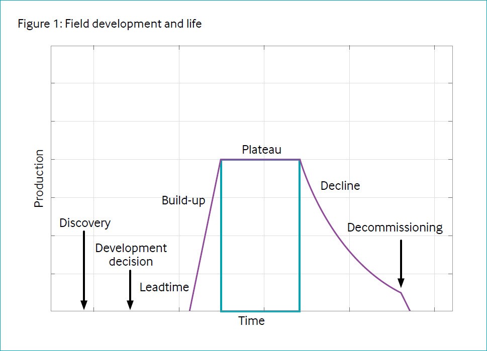
Typically, plants are more efficient (consume less energy per unit of sold product) when operated at a constant rate. Upstream plants are typically designed based on the plateau flow rate. During the depletion (decline) phase, the efficiency typically drops because machines operate far from their optimal working windows (e.g., pumps and compressor may recirculate a larger portion of the flow).
For these reasons, energy efficiency should embrace the entire lifespan of an asset, keeping in mind that a higher efficiency at nameplate capacity does not imply higher efficiency over the full life.
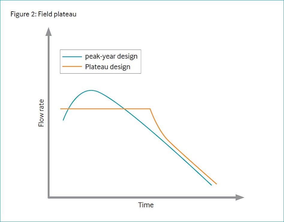
- In the design phase, a ‘peak-year’ design approach should be avoided. The nameplate capacity of the asset could be chosen to have an ‘as-long-as-possible’ production plateau. This also results in smaller facilities, with potential benefits for CAPEX and safety/environmental in general (reduced land usage, smaller inventories of hazardous substances, etc.). Another option is to handle the peak by installing modular or temporary (e.g., rental systems) for the peak ‘increment’. The peak could be accommodated with parallel trains as discussed below.
- Optimize overdesign factors based on production data considering the real probability of occurrence of higher production: avoid applying multiple overdesign factors to design data (reservoir, process, electrical, mechanical departments and detailed engineering); every single overdesign factor should be clearly declared and traced.
- Consider a train approach (3 × 50%; 4 × 33%) on main machines, such as export pumps, booster and delivery compressors, and main power generators, to ensure that optimal efficiency is achievable for different operating modes. A 3 × 50% (or 4 × 33%) design is usually more efficient than a 2 × 100% design during the depletion phase because it prevents machines from being operated at a significantly lower turndown rate.
Energy-efficient best practicies
A general rule of thumb is that companies should focus on sourcing the lowest carbon energy and then utilizing it as efficiently as possible. For example, one trend now is to electrify onshore oil fields as much as possible and try to source low carbon power (solar, wind, etc.) off the grid. All the field gas is then sold instead of combusted onsite for self-use.
Many of the compendium topics contain information related to energy-efficiency best practices for different equipment. The compendium topics should be reviewed as a project kicks off and during a project to determine the applicability of each topic.
Best available energy-efficient technologies
During the design phase, technology selection should include consideration of the best available energy-efficiency technologies. The following criteria can be included when selecting technologies:
- Energy efficiency (and GHG emissions) of the various technologies/vendors.
- Life-cycle cost that includes the CAPEX and all incremental costs/benefits.
- Technology maturity – most energyefficient solutions use proven technology. The use of energyefficiency equipment or systems that do not have several years of operational experience may pose the risk of poor reliability or poor availability of equipment or support services/parts. Therefore, most oil and gas companies are not willing to use unproven technologies.
The design can also incorporate provision for future technologies that are currently at demonstration scale. These include provisions for plot space, tie-ins, and any utility requirements. Some examples include provisions for waste heat recovery, batteries, and/or tie-ins to renewable power sources.
Additionally, when retrofitting and upgrading, cost–benefit analysis should be conducted to consider replacing with best available technology at the time of retrofit instead of just like-for-like replacement.
Several of the IOGP-Ipieca compendium equipment Info Sheets have information related to energy-efficient design at both the equipment and process level. These should be reviewed as necessary during projects. One energy-efficient methodology that can be applied to assets with lots of thermal integration (heating/cooling), such as Liquified Natural Gas (LNG), Gas to Liquid (GTL), and gas plants, is pinch analysis, and this is also included as a separate compendium topic.
General design criteria: Additional topics
Integration of renewable electricity into oil and gas assets
This involves either generating renewable power onsite or purchasing it off the utility grid from a third party (e.g., using a power purchase agreement). Since renewable sources are typically intermittent, they may require advanced systems for power management. This may include operating with a turndown window of existing combustion-driven power generation units and adding energy storage for peak shaving or energy arbitrage. Note that running renewable systems together with combustion systems can lead to suboptimal combustion performance if the existing systems have to be operated at partial load to accommodate the renewable power source. This issue needs to be fully assessed but can be mitigated by using batteries to level load the solar or wind power and/or by shifting demand to match excess renewable power generation (e.g., during the day for solar). Batteries can also be used to provide long-duration backup to remote operations operating on solar or wind power.
Battery energy storage for spinning reserve optimization
Short duration energy storage (e.g., lithium-ion batteries with 30–60 minutes of energy storage capacity) can be used to provide enough backup power to allow a spare gas turbine or engine to be cold started in case of a trip. This will allow existing turbines and/or engines to run at higher utilization rates and thus higher efficiency, while minimizing the need to run any systems in idle mode. Such a strategy may require aggressive loadshedding schemes as well.
Electrification for heat and power
Electrification can help improve overall system efficiency and reliability and reduce costs and carbon emissions. Note that the effectiveness of electrification depends highly on the carbon emission footprint of the electricity and its cost. Common electrification strategies involve:
- Replacing diesel or gas internal combustion engines with grid power, especially smaller units.
- Replacing diesel rigs with gridpowered ones. Frac completions are also being targeted for electrification (efrac).
- Selecting an electric compressor with a variable-frequency drive instead of a mechanically coupled gas turbine compressor.
- Less common is replacing gas-fired boilers and heaters with electric ones. While this would generally result in a less efficient system if power is generated from a combustion system, it could make sense if the power comes from a 100% renewable energy source, such as solar or wind. Sourcing the heat from waste heat recovery would be the other logical first step to consider.
Buildings
Oil and gas companies should consider energy efficiency as they build or revamp existing office space, control rooms, and other buildings. Adopting sustainable building standards (e.g., LEED certification) enables enhanced performance and saves energy while reducing the overall carbon footprint impact.
Insulation
Oil and gas companies have typically insulated equipment and piping to improve flow assurance, assist oil/water separation, maintain boiler feedwater temperatures, and conserve heat in steam and other hot media distribution systems while saving energy. The undertaking of specific studies on insulation solutions helps avoid the overdesign of heating/ cooling systems and provides optimal performance of utilities during the entire asset life. Insulation projects generally have good payback.
Fuel switching
Switching to fuels with lower carbon intensities is an additional lever that can be used to reduce carbon footprint. One example is switching drilling equipment from diesel to natural gas, as long as methane leaks are avoided. Energy efficiency of the overall system needs to be evaluated first before any fuelswitching initiative. For example, when switching from diesel internal combustion engines to gas engines or turbines, specifically in low power applications, the change in technology could lead to a less efficient system but may still save GHG emissions and costs. Fuel switching from diesel to gas can also have co-benefits, such as lower criteria pollutant emissions and a reduction in noise.
Application technology
In upstream processing, energy-efficient design needs to take place from the wellhead to fluid export/disposal. This includes:
- Drilling and completions
- Reservoir (subsurface) – optimizing energy use in the reservoir (e.g., enhanced oil recovery, EOR, injection, water/oil ratio, gas/oil ratio) streams
- Wellhead: injection (e.g., EOR rates/pressures), production (artificial lift, pressures)
- Fluid handling/processing (off-plot design, pumping, separation, treatment, export, disposal, recycling)
- Utilities (electricity/heat/steam generation and/or import)
In downstream processing, some energy-efficient design considerations include:
- Understanding of fuel and steam balances so that the site avoids excess fuel gas and excess steam.
- Optimization of power generation efficiency (cogeneration versus steam turbines, etc.).
- Cooling towers that have good supply temperatures as they help to make plants more energy efficient. For example, with cooler water, refrigeration systems are more efficient, with lower shaft power requirements. Also, large steam condensing turbines can get more power with improved vacuum from cooler water.
- Downstream energy projects can often also improve margin. For example, adding a new heat exchanger can improve energy efficiency, increase unit throughput, and improve cut points, which results in more desirable products. Another example is the addition of a welded plate heat exchanger in an overhead circuit that recovers waste heat but also lowers operating pressure to improve fractionation.
Technology maturity
| Commercially available | Yes |
| Offshore viability | Yes |
| Brownfield retrofit | Yes |
| Years of experience in industry | N/A |
| Years of experience in oil and gas industry | N/A |
Key metrics
| Range of application | All oil and gas industry facilities and processes |
| Energy KPIs | N/A |
| Guideline capital costs: | Capital cost depends on incremental scope added |
| Guideline operational costs: | Energy- efficient designs reduce energy costs, although they may or may not reduce operation and maintenance costs |
| GHG reduction potential | Reductions in GHG emissions are directly related to reductions in power and fuel inputs |
| Time to perform engineering and installation | Designing for energy efficiency is sometimes slightly more complex than traditional design approaches but does not normally add a lot of time if it is considered through the life of the project |
| Typical scope of work description | N/A |
Decision drivers
| Technical | N/A |
| Operational | O&M staffing requirements are similar to facilities designed with traditional approaches. Well-operated, energy-efficient units can also lead to reliability improvements. |
| Commercial | Most energy-efficient solutions use proven technology. Because energy-efficient options are often higher capital, there is sometimes pressure to reduce capital and go with a less expensive/more energy-intensive option. Therefore, it is important to do a life cycle cost analyses and not just look at the capital cost. |
| Environmental | N/A |
| Economic rule- of- thumb |
|
Alternative technologies
Facilities may be designed with various amounts of energy efficiency depending on design choices and trade-offs.
Operational issues/risks
Occasionally, making a facility more energy efficient will make it less reliable.
Some examples of this include:
- Spinning reserve minimization: Opencycle gas turbines typically supply electricity at offshore production sites. Historically, excess gas turbines (the spinning reserve) are operated to ‘protect’ production from plant vulnerabilities, including power generation reliability. These additional spinning gas turbines consume fuel, while making CO2, without any direct benefit. Spinning reserve reduction is about minimizing the number of machines running. By reducing spinning power there can be greater production exposure to power fluctuations. This can be solved with battery or back-up installation and would imply less overhaul maintenance.
- Capacity design can be an issue, as Under-designing a system, which could lead to lost production and an economic loss.
- Some more efficient motors may have less torque, which could occasionally be an issue if not considered in design.
- Heat exchangers might be added to capture waste heat but then might be impacted by fouling and cause lost production. Fouling monitoring control can be included in design, as well as cleaning capability.
Flaring design needs to include metering considering both routine and non-routine (emergency) conditions. In addition to potential production loss, a less reliable system may also increase GHG emissions from additional upset flaring.
One area of risk is the potential conflict between energy efficiency and ‘standardization’, i.e., the drive to use standardized equipment/systems/ modules that might reduce cost and schedule but may not achieve the highest efficiency. Time profile for both production, energy needs/usage and associated emissions is a basic tool to design optimization.
Finally, increased efficiency may add complexity to a design, but provide a more reliable installation as monitoring helps not only GHG reductions but also process optimization.
Several risks to maintaining energy efficiency are covered in the Energy Performance Monitoring and Optimization Info Sheet.
Industry case studies
Case study 1: Electrification of compressors
A sharp decline over several years in field production reduced the thermal efficiency of several large turbo-compressors. The site had a large amount of recycling and used a significant amount of fuel gas to run.
The project installed two smaller electric compressors connected to the national power grid. This eliminated fuel gas usage, generated much less CO2, and was less maintenance intensive.
Case study 2: Replacement of water injection pump impellers
One site replaced the impellers in four water injection pumps. This reduced the discharge pressure from 240 to 200 bar(g) (3500 to 2900 psig), which was satisfactory for the application. This reduced the electricity used by 1.6 MW, which reduced the CO2 emissions by 9000 tonnes/year.
Case study 3: LNG plant inefficiencies
One LNG plant, which began operating in 2009, applied energy efficient designs in several ways that were less common at the time:
- Combined-cycle instead of open-cycle gas turbine drivers.
- All gas turbines running at 100% load instead of having a spinning reserve and some turbines running at less than 100%
- Starter/helper steam turbines on the same shaft instead of only starter/helper motors. This allowed a smaller power station to provide the balance of site power instead of a large power station to also provide helper power.
Case Study 4: Energy recovery from the fluid catalytic cracking process output at a refinery
An early example of energy-efficient design is one refinery’s use of a turboexpander to recover waste energy from the exhaust gas of the regenerator in its fluid catalytic cracking unit.
Fluid catalytic cracking is one of the most important process stages in an oil refinery. This process breaks down low-value, heavy hydrocarbons into lighter, more valuable hydrocarbon products. It uses a fluidized bed of fine catalyst to promote hydrocarbon cracking reactions. As the reactions proceed, the catalyst particles become coated with carbon. This carbon is then burned off in the regenerator. Exhaust leaves the regenerator at approximately 40 psig (3 bar) and 1350 °F (732°C).
The operating company decided to recover the energy in this exhaust stream by directing it into an expansion turbine after separating out any entrained catalyst particles.
Thermal energy and pressure in the flue gas are converted by the turbo-expander into mechanical power, which is used to drive a 24,000 hp axial compressor. This compressor, which is commonly referred to as an air blower, provides both combustion and fluidizing air to the regenerator. Exhaust from the turbo-expander is close to atmospheric pressure but is still around 500°C, so it is directed to a waste heat boiler to generate steam.
By recovering energy from the hot flue gases, the refinery saves up to 22 MW in electricity. The turbo-expander is designed to generate more energy output than the air blower needs, so in certain operating situations, it can export additional power (up to 4 MW) for sale to the grid.