Topic last reviewed: November 2022

Sectors: Downstream, Upstream

Download as PDF

Fuel-fired equipment (e.g., furnaces and boilers) combust fuel with the purpose of releasing chemical energy as heat. For industrial applications, they generate heat or steam for direct use in processes or for operating other equipment such as steam turbines (to produce shaft power) or as enablers for chemical reactions. The information here is applicable for equipment where combustion is occurring, excluding, equipment such as thermal oxidizers, gas turbines, or flare systems.

The combustion efficiency of any combustion process is dependent on the amount of oxidant (air) that is used in relation to the amount of fuel (excess air versus reaction stoichiometry) and on how well they are mixed. Controlling this air/fuel mixture ratio, while still maintaining adequate mixing and minimizing waste heat, is key to maintaining high thermal system efficiencies and minimizing methane slip from incomplete combustion.

Nearly 80% of all the improvements in energy performance in the industry derive from fuel combustion management. Improvements in the original equipment design, increased reliability, waste heat management, proper monitoring, proper maintenance, frequent cleaning, and the use of key operating parameters (oxygen percentage, O2, at arch, draft, etc.) are levers for enhanced energy efficiency.

Some commonly used techniques to decrease fuel usage and improve energy efficiency and combustion equipment performance are as follows:

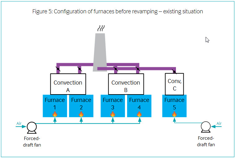
  • Flue gas energy recovery: additional boiler feedwater preheating, steam generation, or steam superheating, combustion air preheating, process preheating, thermal oil heating, fuel preheating
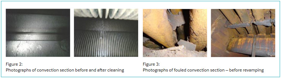
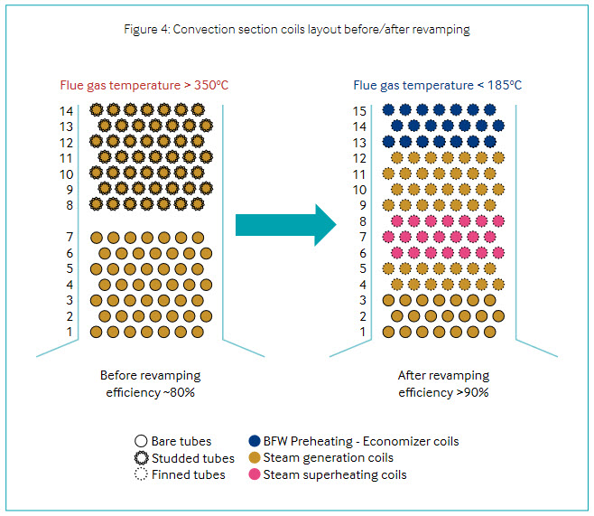
  • Effective continuous monitoring (fuel flow rate, flue gas temperature, excess air, O2, etc.), spot-specific flue gas measurements (carbon monoxide content, nitrogen oxides – NOx, sulphur oxides – SOx, particles), cleaning of heat transfer surfaces (soot blower depending on the fuel type), cleaning of online/offline tubes, proper maintenance, and frequent equipment inspection

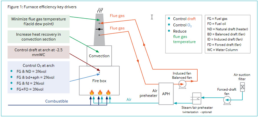
Energy efficiency key drivers for a furnace are illustrated in Figure 1.

For a boiler, the same energy-efficiency guidance principles are also applicable.

Technology maturity

Commercially availableYes
Offshore viabilityYes
Brownfield retrofitYes
Years of experience in industry30+
Years of experience in oil and gas
industry
30+

Key metrics

Range of applicationThese technologies can be used in a variety of applications within oil and gas operations, including, but not limited to, heating systems, power generation, and flue gas recovery
Efficiency (lower heating value)At full nominal load:
  • For boilers, typically from 85% to 95% for latest gas boilers with economizers
  • For furnaces, from 80% to 92% for furnaces with air preheating
At minimum load or other intermediate loads, these efficiencies could be lower
Energy key performance indicators
  • Control draft at arch at −2.5 mm water column
  • Control O2 at arch: 3% volume (typical for mixed fuel oil/fuel gas firing); 2% volume for FG only
Guideline operational costsDepends mainly on fuel costs, air excess (efficiency), soot blower operation (depending onthe fuel), campaign duration, and maintenance frequency.
Typical scope of work description
  • Monitor the combustion equipment’s performance characteristics, fuel usage, and exhaust/flue gas profile
  • Identify potential alternatives for efficiency tune-ups and techniques to improve system performance and reliability
  • Perform a cost feasibility analysis (direct and indirect costs, and length of payback period) for each identified technique/system to improve energy efficiency
  • Implement the selected energy-efficiency improvement systems and techniques

Decision drivers

TechnicalToo high a stack flue gas temperature indicates the potential for more heat recovery and improved efficiency. Flue gas O2 (or CO2) concentrations (too high or too low) are indicative of the potential for improving combustion efficiency by optimizing the input air/fuel ratio.
OperationalTo achieve higher efficiency, it is best to operate continuously, avoiding repeated start-ups and securing stable heat distribution in the equipment.
Environmental
  • Reduce greenhouse gas (GHG) emissions
  • Operating cost savings due to less fuel consumption
  • Reduce emissions of volatile organic compounds, including hazardous air pollutants, NOx, SOx, and other air pollutants
  • Reduce methane slip in exhaust

Opportunities

  • Reduction in environmental impact via GHG emission reduction
  • Reduction of operation costs
  • Improved equipment performance and reliability

Industry case studies

The following two case studies are industry examples of improving the performance of combustion equipment through revamping projects. The first relates to the energy efficiency improvement of a process heater by selectively revamping its convection section for enhanced heat recovery to lower flue gas temperature leaving to the stack. The second case study is also related to energy-efficiency improvement but in this case by the addition of an air preheating system on an existing furnace set.

It is worth mentioning that, prior to energy-efficiency project development, proper and timely maintenance, proper regular cleaning of tubes and the convection section during furnace shutdown, regular control of burners and gas duct integrity, air ingress monitoring, adequate draft control, proper O2 analyser use and calibration, and fuel gas quality control (recommendation is made to stop fuel oil firing) are basic maintenance and cost-effective principles/solutions to ensure that furnace efficiencies are operated at the highest possible standards.

Case study 1: Fired heater energy-efficiency improvement by revamping of its convection section

Energy efficiency is one of the main levers for GHG reduction, reduced operating costs, and operating excellence. On a fired heater, one way to improve energy efficiency is to increase heat recovery in the convection section by adding new process or utility (steam) coils to lower final flue gas temperature leaving to the stack.

Objective

The objective of this study was to determine the most relevant new convection section design to improve the overall efficiency of a major furnace. The constraints were that this new convection section should fit onto the existing furnace radiation box and that the flue gas exhaust should be connected to the existing flue gas ducts to the stack.

The existing convection coil configuration was leading to a poor furnace thermal overall efficiency of about 80% as heat recovery from the convection section was only performed through medium pressure steam generation coils. Flue gas temperature at the stack was typically above 350°C, especially at high furnace loads.

The furnace process duty has increased over the years as a result of improved operating conditions, throughput, and yields without any debottlenecking of the convection section heat recovery.

This furnace is one of the refinery’s largest (45 MW fired duty). It is a natural draft cabin-type furnace, only firing gas (fuel oil firing stopped some years ago), and it was designed in the late 1960s.

Heavy maintenance works were anticipated at the next turnaround as the convection section was still partially fouled due to residual fouling left from the fuel oil firing, and the convection section required frequent cleaning to overcome its poor thermal efficiency. The remaining fouling was confirmed by an unexpectedly high pressure drop on the flue gas side across the convection section.

Figure 2 illustrates the effects of cleaning on a convection section – with the tube fins becoming far more distinguishable whilst Figure 3 illustrates typical fouling,

As demonstrated through this example, liquid fuel oil firing in furnaces can lead to fouling issues and particulate agglomeration if combustion is not properly controlled. Fuel oil firing also leads to higher GHG emissions than gas firing (fuel gas or natural gas). Consequently, the recommendation is to minimize or preferably stop fuel oil firing.

Approach

Furnace simulations were conducted for different convection configurations to identify and select an improved design for the convection coil layout, while ensuring a compromise between additional heat recovery and additional weight/loads on the furnace structure.

Additionally, the simulations performed were also conducted to ensure that additional pressure drop across the convection section would not lead to potential draft issues.

Findings

The current convection section was only made of steam generation coils (50% bare tubes and 50% studded tubes).

To improve overall heater efficiency from approximately 80% to above 90%, a brand-new convection section was designed. Thanks to this new configuration, flue gas temperature at the stack can be reduced to below 185°C.

Around the steam generation coils, the new convection configuration includes the addition of:

  • Steam superheating coils
  • Boiler feedwater preheating coils (economizer)
  • A 15th tube row (free space made available by removal of the soot blower)

As only gas is now fired, finned tubes have also been selected to increase the heat transfer coefficient while the three bottom shock tubes remain bare. New remote draft control was also provided to replace old, manually adjusted draft dampers.

The convection configuration, including process coils in the convection section, was also studied. Eventually, this configuration was not retained as overall efficiency improvement with boiler feedwater preheating, medium pressure steam generation, and steam superheating were higher than with process coils in the convection section (process fluid at furnace inlet was already quite high at >400°C). It should also be noted that radiation tubes would have required a diameter increase to limit an increase in process-side pressure drop.

Conclusions

Furnace energy-efficiency improvement by increasing heat recovery from the convection section is a cost-effective solution. This was helped by using adequate process and furnace simulation tools that allow, in a reasonable time frame, testing of several design configurations. In this specific case, this facilitated an efficiency increase of the 45 MW heater of about 10%

Additional steam superheating and boiler feedwater preheating in this new convection section will not have to be undertaken in other furnaces or boilers.

In addition to the fuel savings, it is estimated the facility will produce approximately 8 kt CO2 less per year.

Case study 2: Fired heater energy-efficiency improvement by addition of an air preheater

On a fired heater, another way to improve energy efficiency is to recover heat from the flue gases into combustion air preheating through an air preheater (APH).

Objective

The objective of this screening study was to determine whether the addition of an APH on an existing set of heaters was technically possible and what the benefits were of this improvement in terms of GHG emissions reduction.

The constraints were that this new APH system had to fit in an existing in- operation asset where plot availability is reduced and its installation had to fit within a typical turnaround window of 45 days oil-to-oil.

The scope was limited to the study of an additional APH system (with its auxiliaries), and no modification to the existing furnaces (neither the fireboxes nor convection sections) was requested to limit capital expenditure and to avoid potential turnaround duration extension.

Existing situation

The existing furnace configuration was leading to a flue gas temperature at the stack of about 260°C for an overall calculated fuel efficiency of 84%.

The typical fuel gas hydrogen sulphide content was leading to a calculated flue gas acid dew point of 100°C. For the same flue gas composition, the water dew point is calculated to be 60°C.

To evaluate different APH technologies/ metallurgies, two performance targets were set for the flue gas temperature at the stack:

  • Case 1: 140°C (40°C margin compared with acid dew point)
  • Case 2: 95°C (35°C margin compared with water dew point)

The challenge in this project was also related to the very specific furnace configurations. The existing furnace configuration is described and shown in Figure 5.

Flue gases to be sent to the new APH system from a stack common to five furnaces, all located within the same process unit:

  • Furnaces 1 and 2 share a common convection section A
  • Furnaces 3 and 4 share a common convection section B
  • Furnace 5 has its own convection section C
  • From each convection section, flue gases are collected and sent to the common stack

Furnaces 1, 2, 3, and 4 are cabin-type furnaces with forced draft and firing fuel gas. Furnace 5 is a cylindrical furnace with forced draft and firing fuel gas.

To limit the project scope, an APH will be designed to enhance the energy efficiency of furnaces 1 to 4, which are the largest ones, with close to 220 MW fired duty in total. Furnace 5 is about 15 MW fired duty.

In the existing configuration, air enters the furnaces at ambient conditions.

Approach

First, furnace simulations were calibrated to represent the existing furnace configurations and operating conditions. Then, several simulations were run with the addition of an APH for furnaces 1 to 4 and with the two target cases for flue gas temperature at the stack (140°C and 95°C)

Once the simulation was performed, the APH and its auxiliaries were sized and installation within the brownfield preliminarily assessed to confirm technical installation feasibility.

Findings

To improve overall heater efficiency, new APH systems have been designed to recover heat from the common stack into furnaces 1 to 4. The APHs also help to slightly reduce the overall quantity of flue gases, which is also beneficial in that in specific cases, such as during summertime, some draft limitations have been observed on those furnaces.

Thanks to this new configuration, the flue gas temperature at the stack can be reduced to 140°C or even 95°C.

To reach 140°C flue gas temperature at the stack, COR-TEN A material was specified for the APH. To reach 95°C, COR-TEN A was associated with a polymer technology or glass-coated tubes to ensure operation below acid dew point without corrosion issues.

Conclusions

The impact of the APH on furnace bridge-wall temperature (+10°C) has been checked and confirmation obtained that the bridge-wall temperature will remain below the acceptable maximum.

Table 1 illustrates the benefits compared with the base case of APH system installation on furnaces 1 to 4.

Regarding burner NOx emissions (increased air temperature will increase NOx emissions), it was preliminarily confirmed that expected NOx emissions will remain significantly below the maximum authorized value of 200 mg/ Nm³.

To conclude, the revamp of the existing furnaces with the addition of an APH is feasible from a process point of view.

Regarding furnace equipment, new burners would most probably be required if revamping of existing ones is confirmed unfeasible. Both solutions (new or revamped burners) are challenging in terms of schedule (burner tests required to confirm new/redesign, four furnaces to be equipped, more than 50 burners to replace or revamp in total). New forced draft fans are required to fight against APH additional pressure drop and maintain the required airflow at the burners for proper combustion control.

In addition to the new high performance APH that needs to be supplied, new induced fans for flue gas extraction and new ducts for air and flue gas circulation are required (ducting will be quite large, heavy, and at elevated height from the ground). Civil works for plot preparation will be significant.

Considering all this, overall project economics show a break-even point for this project in the range of seven years.

Table 1: Air preheater (APH) system installation benefits

Base case (existing situationCase 1 flue gas at 140°CCase 2 flue gas at 95°C
Furnaces fired duty, MW220 (base)204 (−7.3%)197 (−10.5%)
Fuel efficiency, %83.8 (base)89.4 (+5.6)91.5 (+7.7)
Flue gas temperature at stack, °C26014095
Air inlet temperature, °CAmbient162220
Flue gas flowBaseBase −6%Base −9%
APH duty, MW-1216

Conclusion

Energy-efficiency improvement levers on fuel-fired furnaces and boilers are known and technologies are mature. In downstream processes, about 85% of the energy input into processes is for heating, making energy efficiency critical to GHG emission reductions. This is done through improvements to the firing equipment itself but also enhanced heat integration upstream.

In the future, hydrogen firing, electric boilers, and carbon capture on furnace flue gases will likely develop to reach net zero targets of major oil and gas companies.

References

  1. American Petroleum Institute. API STD 560 – Fired Heaters for General Refinery Service, Fifth Edition. 2021
  2. US Department of Energy. “Improve your boiler’s combustion efficiency.” Steam Tip Sheet #4. January 2012

E-mail alerts

Sign up to receive Ipieca's e-news
Climate
Nature
People
Sustainability
Marine spill
Please confirm that you are happy to receive newsletters from Ipieca: