Topic last reviewed: June 2023
Sectors: Upstream
Introduction
Energy, primarily power with some minor heat requirement, is critical to carrying out drilling activities. Energy demands vary between drilling rigs depending on the operations, the type of rig, and the location/environment. For offshore rigs, the energy is normally supplied by diesel engines consuming 20 to 45 cubic metres of diesel fuel per day, depending on demand. For example, a dynamic positioning rig will use more diesel than an anchored rig.
Onshore drilling has typically relied on diesel engines as the drilling rigs are frequently moved and diesel engines are mobilized to supply the short-term power needs. Recently, alternative fuel source use has increased (trucked liquified natural gas (LNG) or compressed natural gas (CNG)) in onshore drilling, as diesel prices were high and natural gas prices were low. Also, connecting drilling spreads to local electrical grids has been shown to reduce emissions and use electricity from lower carbon power sources.
Several measures can be used to reduce energy consumption, the amount of fuel burned, and emissions. These can be divided into two categories:
- Reducing waste energy and improving efficiency
- Enhancing power management
There are several ways to reduce energy demand and enhance power management. The drilling rig can be made energy efficient with good design and well-planned transit and drilling operations. In addition, there are emission reducing technologies and products for drilling rigs. Most of these can be implemented on existing rigs (retrofit). The following measures and equipment are described in this document:
- Well planned drilling operations
- Design and maintenance of the drilling rig
- Positioning and transit of the drilling rig (offshore)
- Choice of heave compensation system (offshore)
- Enhanced flexibility of energy production on the rig
- Closed bus
- Peak shavings of drilling loads
- Heat recovery systems
- Heat tracing
- Optimization of cooling water systems
- Energy storage systems (ESS)
- Introduction of a combined hydrogen and methanol injection system
- Incentives in contracts with rig owners to reduce fuel consumption
- Data analytics and digitalization in internal emission monitoring
- Alternative fuel or power sources
These technologies are not specific for drilling rigs but will improve energy efficiency in many different areas.
Energy management systems implementation, such as the International Organization for Standardisation (ISO) 50001 can help identify new process optimization measures. Several rig owners have achieved ISO 50001 certification. ISO 50001 specifies that targets must be established and followed up to be achieved. Training of personnel is an important part of the management system. If introduced, energy consumption and environmental impact can be reduced, and profitability increased.
Well planned drilling operations
To reduce energy demand on the rig, it is important to plan the drilling operations well. An efficient drilling process lowers fuel consumption per drilled meter and reduces emissions. Automatic mud mixing systems reduce costly mixing mistakes, exposure to hazardous material, drilling time, and emissions. Careful planning by engineers and logistics personnel can reduce downtime and improve efficiency. Integrating a remote-controlled rotating and hoisting cement head with top-drive casing-running operations reduces equipment rig up time, leading to less transition time between casing-running and cementing operations. A reliability centred maintenance (RCM) programme can also reduce downtime, improve safety, and provide better return on investment.
Design and maintenance of the drilling rig
Design and maintenance are also important. Well-designed working areas and living quarters reduce the need for heating and cooling and are especially important in harsh, cold environments, where the need for heating is large. In offshore drilling, hull shape and topside design of the rig create wind drag. If this drag can be reduced, energy consumption can be reduced. Hull and propeller cleaning in dry dock reduces drag in navigation and dynamic position (DP). Other best practices, such as lowering cranes, should be considered.
Positioning and transit of the drilling rig (offshore)
An important factor influencing energy consumption on an offshore drilling rig is how the rig is positioned and how transit operations are performed. Economical speed (also called eco speed or slow steaming) and route optimization during transit operations reduce fuel consumption. The eco speed compared to the full-service speed can reduce fuel consumption by 20 per cent. Moored vessels have far lower energy consumption than dynamically positioned (DP) vessels, because the engines on DP vessels are using energy to position the rig.
Typically, a jackup rig will use 20 cubic metres of diesel per day, an anchored rig will use 32 cubic metres of diesel per day a rig on dynamic positioning will use 45 cubic metres of diesel per day, and light well intervention will use less than 20 cubic metres per day. Diesel consumption will also vary depending on the activities performed. The dynamic positioning rig will use more diesel, but will also complete operations faster, so diesel will be consumed on fewer days.
There are podded azimuth thruster systems on the market, consisting of a variable speed electric motor driving a fixed pitch propellor in a pod submerged outside the ship’s hull. No gears or shaft drives are located between the motor and thruster. Such systems can reduce the propulsion energy requirement by 10–20 per cent compared with traditional mechanical azimuth thruster solutions [Reference 1].
An operator in the North Sea has found that using anchoring instead of the DP system in summer (benign conditions) can reduce diesel consumption by roughly 14 cubic metres per day (420 cubic metres of diesel per month), saving approximately 38 tonnes of CO2/day (1,100 tonnes of CO2/month).
Choice of heave compensation system (offshore)
Selection criteria for heave compensation equipment should be driven by the planned work and risks, and not on expected energy consumption (which will be difficult to estimate). For example, integrity critical work like well testing or other operations with extensive pinned-to-bottom activities may benefit from using passive heave compensation systems such as crown mounted compensators (CMC). Active heave drawworks (AHD) are an effective, and in some scenarios, more precise, means of compensation (drilling ahead, landing blow out preventers, and so on). However, AHD has different risks and operational considerations for well testing and other extended pinned-to-bottom activities. Energy consumption by either type of heave compensation system will be impacted by many factors, including rig design, vessel motion characteristics, metocean conditions at the location, and well design/scope of work (drilling/completion/well testing).
Active heave drawworks (AHD), a fully electric solution, have different energy needs compared to the cylinder rig solution or traditional crown mounted compensator (CMC), because these compensation systems rely on different combinations of hydraulic and electrical equipment. The main advantage of hydraulic equipment is the power-to-size ratio of the actuators and their energy-storing capability. Hydraulic equipment is smaller and lighter than its electrical equivalent, whilst the gas accumulators used in hydraulic systems store temporary energy fluctuations in a cost-efficient manner and will continue to work in the event of a power failure. The disadvantages of hydraulic equipment are the need for a large and heavy hydraulic power unit (HPU) to power the equipment, and the temperature dependency of the system. The placement of the HPU on the rig can be problematic, especially for floaters. The properties of hydraulic fluid vary with temperature and can have an impact on the overall performance of the system. Overall efficiency of electrical systems is 85–90 percent compared with about 70 per cent for a hydraulic system [Reference 2]. This increased efficiency makes electric power the preferred option for high-powered equipment. Electrical systems also allow accurate control of both torque and speed and eliminate the environmental hazard of hydraulic fluid leaks. The main limitation of the electrical system is energy storage, which is typically in the form of large, heavy batteries. One disadvantage of AHD systems is the use of AC-powered drawworks, which can be noisy in a confined work environment.
Enhanced flexibility of energy production on the rig
Enhanced flexibility in energy production can be achieved by using power management systems and applying a power load strategy. The intention would be to run the generators at the correct load rather than run all generators on idle. To enable this, a mix of different power output (sizes) of generators can be used. Alternatively, operating most generators on optimum load and one or two generators on variable load can be a solution. Simple electrical power distribution systems can reduce the frequency of blackouts by reducing the number of assignment systems and crossover connections. Where system components are fewer and more efficient, production and maintenance costs will be reduced, and the equipment room will have a smaller footprint.
Closed bus
A rig owner has identified the potential of reducing carbon emissions. According to the company, dynamically positioned drilling units typically operate in high voltage (HV) split-bus or open-bus configurations, with the power management switchboards operating in silos. More engines must be online than might be needed for the total operational loads, potentially increasing emissions. However, by upgrading the power management systems to allow for closed-bus mode, which ties the switchboards together, the power plant can run with fewer engines and optimal loads, the company concluded. Analyses suggested that DP rigs operating in closed-bus configuration could reduce their annual CO2 emissions by 4,800 tonnes per year, and achieve a significant fuel saving, with engine running hours cut by 20 per cent. With fewer engines online, maintenance savings will also be high [Reference 3]. With closed bus, there could be a higher risk of blackout of the power system. This risk must be included in the total evaluation.
A rig owner currently has most of its active fleet modified for closed bus, two engine DP operations (running the minimum number of engine rooms possible at any time to reduce carbon emissions) [Reference 4].
Peak shavings of drilling load
A rig owner has installed a solution on two rigs, which allows peak shaving of drilling loads. Fewer generator sets can run at higher and steadier loads, reducing fuel consumption and carbon emissions. Power management of the generators in operation is also important, such as ramping duty up and down to match demand and minimize fuel consumption [Reference 5].
Heat recovery systems
Heat recovery systems used to recover heat from exhaust gases and other sources, such as jacket cooling water and fuel oil purifiers, can be used instead of heat production from steam boilers, thermal oil boilers, or electrical heaters. This will also serve to reduce energy consumption. The heat can be converted to electricity through organic Rankine cycle modules.
An operator in the North Sea has found that introducing waste heat recovery (WHRU) on main power generation on six different drilling rigs, reduced the need for electrical heating. Average diesel consumption was reduced by 2,000 cubic metres per year and CO2 emissions were reduced by 5,400 tonnes of CO2 per year.
Heat tracing
An operator in the North Sea has found that energy demand could be reduced by lowering the heat tracing temperature, resulting in a reduction of diesel consumption of 600 cubic metres per year and emissions diminished by 1,600 tonnes of CO2 per year (based on the average of 4 rigs).
Optimization of cooling water system
An operator in the North Sea has discovered that energy demand could be decreased by optimizing the cooling water systems, making the pumping more efficient. This was done on four drilling rigs, reducing diesel consumption by 450 cubic metres per year, and a CO2 reduction of 1,200 tonnes per year.
Energy storage systems (ESS)
By introducing a hybrid solution with batteries included in the power system, the diesel generator can run more stably and efficiently. Experience from an operator on a rig in the North Sea suggests that a hybrid solution could reduce diesel consumption by 2,500 cubic metres of diesel per year, a CO2 reduction of 6,800 tonnes per year.
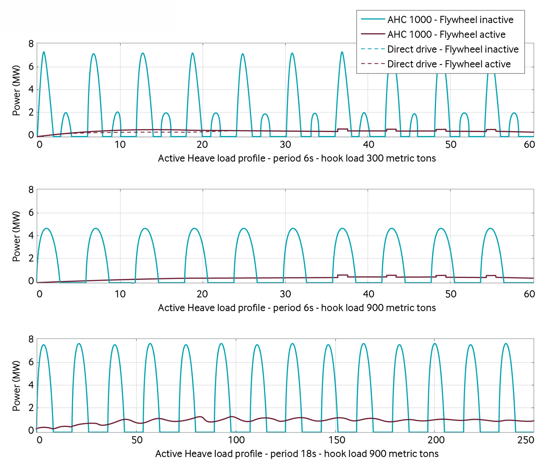
A flywheel is a mechanical device that stores rotational energy. It is a heavy wheel attached to a rotating shaft to smooth the transfer of power from an engine to a machine. The inertia of the flywheel opposes and moderates fluctuations in the speed of the engine and stores the excess energy for intermittent use. An example of flywheel-based energy storage system for offshore drilling is shown in Figure 1. A detailed simulation of heave compensating drawworks, and a mathematical model of flywheel dynamics, was used to analyze the anticipated performance of a large-scale flywheel-based energy storage system. Fuel consumption was based on the characteristics of a diesel generator set. The simulation showed a reduction of up to 75 per cent in average electric power demand and up to 90 per cent in peak power draw [Reference 6]. The simulated load profiles are shown in Figure 1 below.
Introduction of a combined hydrogen and methanol injection system
European operators remain at the forefront of incentivizing investment in greener technologies, not only in Europe but also globally, as recently demonstrated by an operator in Latin America. The operator has recently contracted a drillship. Fuel consumption is expected to reduce by 10– 15 per cent with the introduction of a combined hydrogen and methanol injection system and other efficiency upgrades. With these modifications, emissions of CO2 are expected to diminish by 10–15 per cent, and NOx by 30–80 per cent [Reference 7].
Incentives in contracts with rig owners to reduce fuel consumption
The rig operator is usually not the field operator. Practical consideration in the lead up to drilling could include inclusion of energy efficiency criteria in tender evaluations and contractual instruments to minimize fuel consumption.
A measure to reduce diesel consumption on an offshore drilling rig is to make the rig owner, not the operator, pay diesel consumption, and introduce other beneficial measures in the contract where the rig owner gets compensated for efficient operations. The rig owner operates the rig and is best placed to save fuel cost. One operator in the North Sea changed the incentives for fuel payment and other compensations for six drilling rigs. Diesel consumption was reduced, on average, for one rig by 750 cubic metres of diesel per year, a reduction of 2,000 tonnes of CO2 per year.
Data analytics and digitalization in internal emission monitoring
Efficiency can be increased by digitalization and using data analytics in internal emissions monitoring. Some suppliers are using their own analytics software to monitor and reduce fuel use and emissions on rigs. For example, one supplier has a system which allows real-time tracking and analytics of greenhouse gas (GHG) emissions and fuel efficiency through Power BI dashboards deployed across the fleet. In 2021, it was installed on 14 rigs, and the goal was to have it fleetwide [Reference 8].
An operator is installing its Smart Equipment Analytics (SEA) tool on 19 rigs. This is a dashboard that provides real-time data for monitoring equipment health, inferred emissions, energy consumption, and power plant performance. Another operator has its energy and emissions meters on two rigs and plans to roll out to the rest of their fleet [Reference 9].
An operator in the North Sea noted that updating analytic software for improved management of the generators led to less diesel motors needed to run in parallel, and energy efficiency was improved. Diesel consumption was reduced by more than 300 cubic metres per year, resulting in a reduction of 1,000 tonnes of CO2 per year.
Alternative fuel or power sources
One option for lowering drilling GHG emissions, is to switch from diesel to lower carbon energy. Although infrastructure and logistics are limiting factors, platform rigs have been identified as a potential candidate for shore grid power. The transience of mobile offshore drilling units limits the reach of this technology, but when offshore drilling rigs are at port it could be possible to connect to the shore grid. There is a significant move in onshore operations to replace diesel with gas, grid electricity, or a combination of both. This fuel switch is enabled by rigs that are already electrified, that is, using electric motors driven by standalone gensets onsite. Use of biofuel or biodiesel for rig engines should also be evaluated, such as a full switch or partial switch where some biofuel is added.
Gas-driven rigs
Diesel internal combustion engine (ICE) gensets can be replaced with 100 per cent gas driven ICEs, using either compressed natural gas (CNG) transported by trailers and stored onsite, pipeline quality gas, or associated “field” gas. If gas lift is used at the wellhead, the gas delivery infrastructure may already be in place. While the actual energy efficiency of a diesel ICE may be similar or slightly higher than a gas ICE, overall, CO2 emission reduction of 20-25 per cent can be expected, as well as a decrease in NOx and possibly other pollutants. Other benefits include cost savings (gas is generally cheaper than diesel), noise reduction, and, in the case of CNG, fewer truck deliveries compared to diesel. One operator decided to convert most of its drilling operations from diesel to 100 per cent natural gas fuelled rigs in late 2012. By September 2014, ten of the largest drill rigs were retrofitted with rich-burn gas engines and fuelled entirely by natural gas. By operating on field gas half of the time and LNG for the remaining half, the operator found significant savings per month on its gas engine rigs versus its comparable diesel fuelled rigs [Reference 10].
Gas-driven completions
A related opportunity is to lower the carbon footprint of hydraulic fracturing spreads by replacing diesel with natural gas in dual fuel/dynamic gas blending engines that can use up to 85 per cent natural gas or turbines running on 100 per cent natural gas.
Grid-connected rigs
Another option is to connect the rigs directly to the utility grid, assuming the GHG emissions of the grid are lower than a diesel genset. Fields that import power from a local utility, or with onsite renewables (solar, wind, tidal), could benefit. GHG and NOx reductions of up to 100 per cent are possible, depending on the source of the electricity. Additional electrical infrastructure may be required (for example, VFD, transformers) as is recurring grid tie-ins, as the rigs move from well to well. A temporary connection to the power grid is also a possibility offshore rigs at port could investigate.
Successful implementation of a utility power drilling program can have substantial economic and footprint benefits for an Exploration and Production (E&P) company. Utility power may not always be the answer. Some locations may lack sufficient infrastructure to meet the demand without significant investment, thus, it is necessary to maintain the diesel generators. There may be opportunities for the E&P company to realize savings by negotiating a reduction in rig rates, as the generators will not run continuously [Reference 11].
Technology maturity for rig design, planning, and management
The technology maturity for the four design and operational practices are illustrated in the table below:
- Well planned drilling operations
- Design and maintenance of the drilling rig
- Incentives in contracts with rig owner
- Positioning and transit of the drilling rig (offshore)
| Commercially available? | Yes |
|---|---|
| Offshore viability: | Yes |
| Brownfield retrofit? | Yes |
| Years experience in the industry: | Less than 20 |
Key metrics for the topics above
Range of application | Upstream |
|---|---|
Efficiency | N/A |
Energy KPIs | Energy used per drilled meter, diesel consumption per drilled meter, emissions per drilled meter |
Guideline capital costs | Good design and upfront planning of a new rig will save cost and energy consumption in the long term. |
Guideline operational costs | Well planned drilling operations, incentives in contracts, and use of energy management systems, will save energy and fuel consumption. |
Time for engineering and installation | 1 to 24 months Designing for energy efficiency is sometimes slightly more complex than traditional design approaches but does not normally add a lot of time. An energy management system should not take more than a couple of months to start, though it may take up to two years to run smoothly and have all operational disciplines involved. Incentives with the rig owner are normally added in new contracts. |
Typical scope of work | In the design phase of a new offshore drilling rig, it is important to plan the well carefully to minimize energy consumption. This can be done through cooperation between operators with drilling experience and the rig owner. Input from drilling engineers, process engineers, mechanical engineers, as well as environmental engineers, will be needed. Incentives in contracts with rig owners and introducing an energy management system are normally done with new contracts. |
Decision drivers for the topics above
| Technical | Design |
|---|---|
| Operational |
|
| Commercial |
|
| Environmental |
|
Technology maturity for energy efficiency improvement options
The technology maturity for the eleven technologies/products are illustrated in the table below:
- Choice of heave compensation systems
- Enhanced flexibility of energy production on the rig
- Closed bus
- Peak shavings of drilling loads
- Heat recovery systems
- Heat tracing
- Optimization of cooling water systems
- Energy storage systems (ESS)
- Introduction of a combined hydrogen and methanol injection system
- Data analytics in internal emission monitoring
- Alternative fuel or power sources
| Commercially available | Yes |
|---|---|
| Offshore viability | Yes |
| Brownfield retrofit | Yes |
| Years experience in the industry | 5 to 10 |
Key metrics
| Range of application | Upstream |
|---|---|
| Efficiency | All these technologies will improve efficiency. Examples of reduced fuel consumption are given in the text above. |
| Guideline capital costs | Depending on measure. Good design and upfront planning of a new rig will save costs in the long term. These technologies can also be retrofitted |
| Guideline operational costs | Lower fuel consumption (diesel). More efficient drilling will save on operational costs. |
| Time for engineering and installation | 1 to 12 months for planning, and 1 to 12 months for retrofit installation (will depend on measure). |
| Typical work description | In the design phase of a new offshore drilling rig it is important to plan the well carefully to minimize energy consumption. This can be done through cooperation between operators with drilling experience and the rig owner. Input from drilling engineers, process engineers, mechanical engineers, as well as environmental engineers will be needed. Retrofit cost evaluations must be performed for installation of the technologies described. Energy efficiency evaluations can also be performed on power generation and heating equipment. Process, mechanical and electrical engineers can consider, for example, substituting old heaters with waste heat recovery units, or installing more efficient generators. Such modifications may be costly and will depend on the measure evaluated. The capital cost of the modifications should be compared to the operational savings of lower energy/fuel use and greenhouse gas (GHG) emissions, before deciding to replace old heaters or upgrade the power management system. |
Decision drivers
| Technical: | Design |
|---|---|
| Operational: | Technologies that improve energy efficiency will reduce fuel consumption. Automation, improved power management system, and software upgrades, reduce personnel needs. |
| Commercial: |
|
| Environmental: |
|
Operational issues/risks
Hazard analyses should always be carried out.
Opportunities/business case
- Efficient drilling operations and design programmes will contribute to delivery of wells quickly and with lower energy consumption, reducing costs
- Reduced fuel firing can lower greenhouse gas emissions
- Reduce noise
References
- Langley, D. ‘Shedding light on electrical simplicity.’ In Drilling Contractor: The Efficient Rig, 21 September 2011.
- Tapjan, R. and Kverneland, H. ‘Hydraulic vs electrical rig designs: pros and cons on floater heave compensation systems.’ In Drilling Contractor: The Efficient Rig, 8 September 2010.
- Offshore staff, ‘DP modifications could cut rig emissions.’ In Offshore, 25 October 2021.
- Cordova, P. ‘Offshore drilling gearing up towards the Energy Transition.’ In S&P Global Commodity Insights, 11 August 2021.
- Cordova, P. ‘Offshore drilling gearing up towards the Energy Transition.’ In S&P Global Commodity Insights, 11 August 2021.
- Williams, K. and de Jone, H. ‘Hybrid heave drilling technology reduces emissions, operating costs for offshore drilling.’ In Drilling Contractor, September/October 2009.
- Cordova, P. ‘Offshore drilling gearing up towards the Energy Transition.’ In S&P Global Commodity Insights, 11 August 2021.
- Cordova, P. ‘Offshore drilling gearing up towards the Energy Transition.’ In S&P Global Commodity Insights, 11 August 2021.
- Cordova, P. ‘Offshore drilling gearing up towards the Energy Transition.’ In S&P Global Commodity Insights, 11 August 2021.
- McEvers, J. and Kent, B. ‘Drilling with 100% natural gas engines.’ In SPE-173072-MS. SPE/IADC Drilling Conference and Exhibition. London, England. March 2015.
- Marchiano, M, et. al. ‘Utility power for onshore drilling rigs: an application guide.’In 2019 IEEE Petroleum and Chemical Industry Committee Conference. Vancouver, Canada. 9-12 September 2019.