Topic last reviewed: June 2023
Sectors: Downstream, Midstream, Upstream
Introduction
Power recovery turbines (PRTs) are pumps that operate in reverse, to recover energy from a process and improve overall system efficiency. A PRT is a single or multistage pump or turbine that is used when a fluid is pressurized and there is a downstream requirement for pressure reduction. Rather than throttle the fluid pressure through a pressure reducing valve and waste the energy, a PRT can be used to drop the fluid pressure and turn the turbine impeller, driving a generator or drive shaft to other rotating equipment, for example, a pump or compressor. This way, some of the energy can be recovered, minus the efficiency losses of the PRT. In some processes, particularly in cryogenic liquefaction, the enthalpy reduction when using the PRT will increase the overall efficiency of the liquefaction process. While the scope of the PRT technology in this info sheet is for energy recovery from high-pressure liquids, energy recovery is also possible from high-temperature and high-pressure gases – please refer to the Gas turboexpanders info sheet.
The impact of the PRT needs to be considered in relation to the overall system efficiency, as generating additional power will reduce the need for power generation or importation. Additionally, the impact on the process needs to be considered. This may provide additional drive or constraints for the installation of this equipment. This includes selection of suitable motors ratings which are suitable to work without PRT if the liquid source for the PRT is not available during start up. This ensures that the pump can be started up run when the PRT is unavailable. For typical configurations, refer to American Petroleum Institute API 610 12th edition Annex C [Reference 1].
Application of technology
A PRT is typically used as a secondary driver inline to a primary drive motor and a process compressor and acts as trim power to the system. A PRT may be used to drive an electric generator but use as a standalone driver is less common.
A train arrangement may contain a motor as primary driver and a primary pump. The PRT system would add a PRT, an over running clutch, bypass control valve and shaft. As supplemental power is available, the PRT and clutch would be engaged and allowed to drive the secondary equipment shaft, thereby reducing the output of the primary motor and lowering fuel or electricity costs.
The most common PRT application, when used with a liquid, is simply a standard centrifugal pump running in reverse. This application, however, will have a narrow efficiency operating range. A PRT specifically designed for power recovery will be able to run efficiently over a wider flowrate range, and may include modifications to inlet and outlet nozzles, blade profiles, bearings, and seals. The performance characteristics of a PRT, in some respects, are like those of a centrifugal pump running in forward direction, so the manufacturer should be contacted when using a pump in a PRT application. Multi-stage designs are also available. For cryogenic services, hermetically sealed pumps with wetted generators are available.
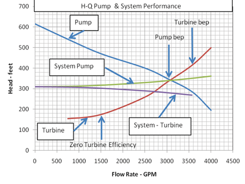
The PRT efficiency curve typically follows the same behaviour as a centrifugal pump, with a maximum efficiency that is similar, or slightly higher, than that of the equipment when it is being used as a pump. PRTs normally have a minimum flowrate requirement that is slightly higher than that of a centrifugal pump, below which the PRT begins to consume power, rather than generate it [Reference 2]. Figure 1 is an example of the performance of a centrifugal pump versus flow rate when the pump is operated as a pump and as a power recovery turbine. In the diagram, BEP refers to best efficiency point.
It is important to note that because the generated power operating exceeds that supplied by a motor when operating as a pump, the mechanical design needs to be evaluated to ensure that design limits are not exceeded.
A PRT may operate in a fixed head or fixed speed format. Pump affinity laws are still applicable. Although PRTs are commercially available, they are far less common than typical pumps and turbines, and there are fewer suppliers. API 610 gives additional requirements and guidelines to PRT applications [Reference 4].
For brownfield applications, the effect on the train rotodynamic should be carefully evaluated if the PRT is installed at a later stage. The use of a foot mounted clutch is suggested to avoid this issue, if provided by different manufacturers. This would require more space but would reduce problems. Also, the impact of additional power generation would need to be evaluated in relation to the impact on the overall energy generation. It is important to ensure that the power recovered from the PRT application(s) does not cause the power generation systems to operate at minimum turndown (or at significantly reduced efficiency), as this would reduce the overall system efficiency. An additional consideration is the stability of the process used to drive power generation, which could lead to instability of the power grid.
Additionally, in specific applications, such as liquefied natural gas (LNG) technologies, the power recovered by PRTs (via generators) is only a small bonus. The real incentive is reducing enthalpy of the high-pressure liquid being expanded, such that the production capacity of the entire plant is increased by deeper cooling of refrigerant and by reducing flash gas regeneration that requires higher power.
Incorporation of PRT is best considered during design, as retrofitting may be difficult, depending on the brownfield situation (such as space, location and so on). However, in locations where the PRT could be applied later, provision for tie-ins and plot space could be incorporated in the design.
Installation viability should be evaluated over the life of the field, due to the varying flowrates and pressure profiles.
Technology maturity
| Commercially available | Yes |
| Offshore viability | Yes |
| Brownfield retrofit | Yes |
| Years of experience in the industry | 21+ |
Key metrics
| Range of application | Systems with a liquid under pressure that is required to be at a lower pressure downstream due to process requirements. For example:
Potential future applications: |
|---|---|
| Efficiency | 40% to 80% typical of turbine, but efficiency will be less than a typical pump or compressor at the same flowrate This is defined by: |
| Energy Key Performance Indicators (KPIs) |
|
| Guideline capital costs | Design, equipment, installation; cost dependent on project design and scale. The cost is dependent on:
|
| Guideline operational costs | Potential to produce power from excess or stored energy will reduce total plant energy generation costs (operational costs), minus any related maintenance costs for the PRT, minus the incremental design cost due to the application. Typical recovery is up to 1 MW. Extra bypass is likely to be required for startup, control, and to mitigate reliability issues. |
| Greenhouse gas (GHG) reduction potential | Power produced by a PRT can reduce on-site power generation or power import, thus reducing either scope 1 or scope 2 emissions. This improves overall plant energy efficiency, thereby also reducing overall GHG intensity. The net benefit calculated should include power generation efficiency. |
| Time to perform engineering and installation | 6 to 18 months Depending on whether the equipment is off the shelf (6 months) or customized. This could be a long-lead item depending on availability of the equipment and requirement for special materials of construction. |
| Typical scope of work description | The use of a PRT should be included in the initial development of a system due to piping and space requirements. The range of operation should be known, and equipment specifications and data sheets should be created. If used in an inline arrangement, the motor and other components should be compatible with the PRT. The equipment may or may not be skid mounted. Specifically for upstream, the applicability of the PRT is to be considered over the life of the field, due to various production flow, pressure, and contaminant profiles. Provisions for future tie-in and installation can be considered. |
Decision drivers
| Technical |
Specifically for upstream:
|
| Operational |
|
| Commercial |
|
| Environmental | N/A |
Alternative technologies
There are currently no known alternative technologies. Advancements are made to improve efficiency and power recovery for various applications.
Operational issues/risks
The application of a PRT should consider the full range of expected operation. There may be cases where the PRT is not utilized or available. If a system has a wide range of fluid flows but the PRT is only effective over a narrow range, then it may be bypassed during those cases. A PRT may lose efficiency and have mechanical problems when two phase flow is present. A protection system should be included to cut process stream through the PRT to avoid overspeed. For cryogenic service, it is important to have vapour pressure control for wetted cryogenic generators and bearings. This is to ensure that there is a margin between operating pressure and vapour pressure of the liquid, and that vapour does not enter the bearings. For certain services, recent developments include PRTs that will allow for two phase flows, which can be explored if two phase flow is continuously present, offering advantages where the conventional PRT cannot be used.
Fluid quality issues can also hamper PRT performance by either corroding or plugging the turbine blades.
Opportunities/business case
While liquid hydraulic power recovery turbines may only capture a few megawatts at a time, this can have an overall effect on reducing net total energy. By using liquid expanders on chilling systems, even if the power obtainable is not high, there is additional benefit in chilling duty provided, instead of throttling through a valve.
Industry case studies
Energy recovery in oil refineries by means of a PRT handling viscous liquids [Reference 5]
A PRT was installed to recover energy within a hydrogen sulphide removal unit, replacing a pressure reducing valve. The PRT recovered electric energy of 349.3 kW to the feed pump, leading to an annual electric energy recovery of 2966 MWh and a maximum payback period close to nine years, considering the installation, the carbon dioxide equivalent (CDE) allowances, and both operational and maintenance costs.
References
- API STD 610 Centrifugal pumps for petroleum, petrochemical, and natural gas industries.
- Budris, A. ‘Optimizing efficiency when pumps are operated as both pumps and power recovery turbines.’ In Waterworld Magazine. 2010. Giardinella, S., Chung, K., Ávila M, López, D. ‘Improve energy efficiency using hydraulic power recovery turbines.’In Chemical Engineering. 1 June 2017.
- Budris, A. ‘Optimizing efficiency when pumps are operated as both pumps and power recovery turbines.’ In Waterworld Magazine. 2010.
- API STD 610 Centrifugal pumps for petroleum, petrochemical, and natural gas industries.
- Rossi, M. Comodi, G. Piacente, N. Renzi,M. ‘Energy recovery in oil refineries by means of a hydraulic power recovery turbine handling viscous liquids.’ In Applied Energy, 270:115097, July 2020.
Other references
- Lobanoff, V. and Ross, R (2019). Centrifugal Pumps: Design and Application. 2nd edition, Gulf Professional Publishing.
- UN Climate Technology Centre & Network. Global warming countermeasures: japanese technologies for energy savings/GHG emissions reduction,. 2008.