Topic last reviewed: November 2022
Sectors: Downstream, Midstream, Upstream
Category: Efficient use of power - pumps
Pumps are used throughout the petroleum and natural gas industry for different exploration and production processes as well as oil and gas transportation and refining applications.
Typical pump applications include:
- Feed and product oil transfer
- Utility water supply (e.g., cooling water, boiler feedwater, etc.)
- Fire-water supply
- Chemical injection
- Process fluid transfer
This info sheet focuses more on centrifugal pumps, as the majority of power-consuming pumps are this type and does not include submersible pumps and gas lift pumps, which are covered in the Energy Efficient Design Info Sheet. Pumps come in an extensive range of sizes and multiple types. Pumps are more generally classified into two groups based on the way they add energy to a fluid: positive displacement pumps and centrifugal pumps. Positive displacement pumps pressurize the fluid directly, while centrifugal pumps (also called ‘rotodynamic pumps’) speed up the fluid and convert this kinetic energy into pressure.
In general, more than 90% of pumps in the oil and gas industry are centrifugal as they are capital/energy efficient and require less maintenance.
Centrifugal pump application
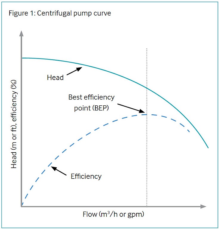
A centrifugal pump curve is illustrated in Figure 1 which plots pump head (usually measured in metres or feet), and efficiency (usually calculated as a percentage) on the Y-axis against pump flowrate on the X-axis (usually measured in cubic metres per hour or US gallons per minute).
The best efficiency point (BEP) is the flow rate with the highest efficiency.
It is described as the point at which a centrifugal pump is operating at its highest efficiency, transferring energy from the prime mover to the system fluid with the least amount of loss. The pump should be operated as close to BEP as possible, as there are not only efficiency and thus emissions benefits but also reliability benefits as pump vibration increases and mean time to failure decreases the further the duty moves away from the BEP.
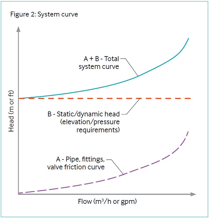
The system that the pump operates in is dependent on the sum of both:
- the friction in the system generated by the pipe, valves, fittings, and equipment
- the elevation or pressure requirements
This is illustrated in Figure 2.
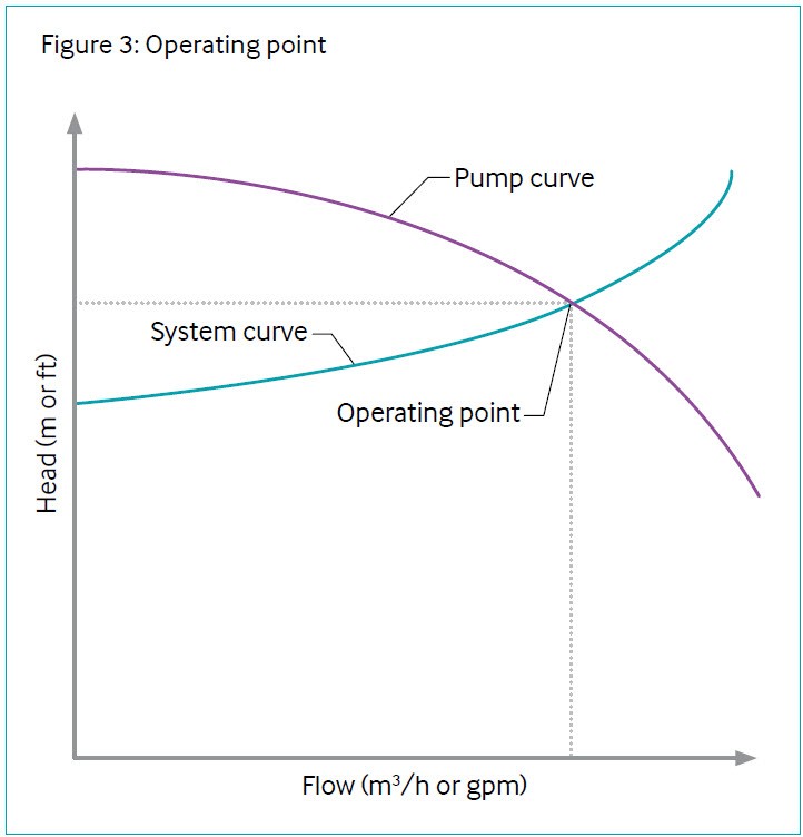
The pump operating point is where the centrifugal pump curve (black) and the system curve (grern) intersect, as illustrated in Figure 3.
Changes in centrifugal pump curves can be estimated from the following (known as the ‘fan laws’ or ‘affinity laws’):
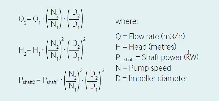
These are centrifugal pump curve changes. The actual operating point will be dependent on the intersection with the system curve, as previously illustrated in Figure 3.
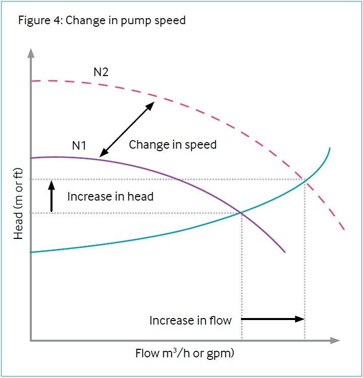
Figure 4 shows the pump is operating at a speed N1 and the operating point is where the centrifugal pump curve (black) intersects the system curve (green). If the speed is increased to N2, there is an increase both in the head and the flow rate. This is different to a speed change on a reciprocating pump, where the discharge pressure is unaffected by speed changes. Regardless of the pump type, speed control can be an energy-efficient method of control for friction-dominated systems.
Common issues with pumping systems
Centrifugal pump efficiency will usually increase with pump size as flow rate increases. At lower flow rates, positive displacement pumps should be considered. Often, pumping system problems occur from improper pump selection and operation, later producing considerable maintenance needs and loss of energy efficiency. Examples of these problems include inefficient operation, poor flow control, internal recirculation, and high maintenance. Due to the mechanical nature of pumps, they are also subject to wear, erosion, cavitation, and leakage.
A pump’s efficiency can degrade as much as 10–25% before it is replaced. Efficiencies of 50–60% or lower are quite common in degraded pumps [Reference 1]. However, because these inefficiencies are not readily obvious, opportunities to save energy by repairing or replacing components and optimizing systems are often overlooked. A starting point to tackle system problems is to perform a system assessment, which reviews the operation of a pumping system, often using certain tools to help identify inefficiencies in the system, determine improvement measures, and estimate potential energy savings.
Pumps are often operated over a wide range of flow conditions. A key to improving system performance and reliability is to fully understand system requirements (peak demand, average demand, and the variability of demand) on a daily and yearly basis. This information should be used to match flow and pressure requirements more closely to system needs. In matching pumping equipment to loads, pumps should be sized to maximize the amount of time that a pump operates at or near its BEP. A control valve too open or too closed is one of the possible signals of system inefficiencies. A more detailed description of the efficiency improvement opportunities and types of system improvements that can be made follows.
Efficiency improvement opportunities in system design
This section describes key improvement opportunities in pumping systems to assist operators and engineers in reducing energy use and prolonging the durability of pumping systems. As a rule of thumb, benefits from efficiency improvement will be likely if the system has flow rates that vary by 30% or more from the BEP and system imbalances greater than 20%. Software tools such as the Pumping System Assessment Tool (PSAT) of the US Department of Energy (DOE) provide estimates of optimal efficiency [Reference 9].
Oversized pumps
Oversized pumps are often a result of conservative engineering practices where a margin of safety is included to compensate for pump sizing or where service requirements have changed (e.g., a decrease in the production rate). This can be a result of poor understanding of the flow requirements (peak flow, average flow, and variability) or because of uncertainties in the design process. The tendency to design pumps larger than the system requires may also occur due to anticipated expansions in system capacity and potential fouling effects.
Issues with oversized pumps frequently develop because the system is designed for peak loads, while normal operating loads are much smaller, which means excess flow energy is being applied to the system. This excess flow energy translates into increasing operating costs due to the additional energy used to run a larger pump. It also generates unnecessary wear on components such as valves, piping, and piping supports, which eventually increases maintenance requirements. These costs are often overlooked during the system specification process. Since many of these operating and maintenance costs are avoidable, correcting an oversized pump can be a cost-effective system improvement.
Indications of oversized pumps include:
- Use of high bypass flow rates
- Throttled flow control valves
- Frequent replacement of bearings and seals
- Excessive flow noise
- Intermittent pump operation
An obvious solution is to replace the pump/motor assembly with a downsized version; however, this may be costly and may not be feasible in all situations [Reference 2]. Instead of replacing the entire pump/motor assembly, alternative measures may be evaluated, including:
- Replacing the impeller of the existing pump with a smaller impeller and stator (volute/diffuser) – this applies to centrifugal pumps only
- Reducing the outer diameter of the existing impeller (applies to centrifugal pumps only)
- Installing an adjustable speed drive (ASD) to control the pump if the flow varies over time
- Adding a smaller pump to reduce the intermittent operation of the existing pump (e.g., pony pumps)
Improvement of fluid properties
The properties of pumping fluid affect the efficiency as well. A fluid with higher viscosity provides a lower pump efficiency. This issue can be resolved by increasing the operating temperature. Caution should be given to the net positive suction head (NPSH) available versus the NPSH required to avoid pump cavitation since the increased fluid temperature will affect the vapour pressure of the suction fluid, which is not preferred from a cavitation perspective.
Efficient piping configurations
In systems dominated by friction head (the amount of energy used to overcome resistance to the flow of liquids through the pumping system, usually in units of feet or metres) there are multiple energy opportunities that work by reducing the power required to overcome the friction head. The frictional power required depends on the flow rate, fluid pressure, pipe size (diameter), overall pipe length, fittings installed (valves, junctions, etc.), pipe characteristics (surface roughness, material, etc.), and properties of the fluid being pumped.
Optimizing the configuration of the pumping system involves several steps, which include determining a proper pipe size, designing a piping system layout that minimizes pressure, and selecting fittings with low pressure drops. Determining the proper pipe size involves weighing the initial cost of the pipe against the cost of pushing fluid through it. Although larger pipes create less friction loss for a given flow rate, they have higher material and installation costs. Although piping system layouts are usually subject to space constraints, there are often chances to minimize unnecessary pressure drops by avoiding sharp bends, expansions, and contractions and by keeping piping as short and straight as possible.
A key configuration improvement is to establish a uniform velocity flow profile upstream of the pump. Poor flow profiles are a result of inefficient piping configurations that promote uneven flow, excessive pre-rotation, and/or turbulent flow, which diminishes pump performance. Consistent velocity profiles can be achieved by ensuring a straight run of pipe leads into the pump inlet. If an elbow must be placed just upstream of the pump due to space restrictions, a long radius elbow should be selected. To correct any disruption in flow in the elbow, a flow straightener, such as a baffle plate or a set of turning vanes, should be installed with an elbow. A flow straightener creates a more even velocity profile but consideration should be taken to ensure that the pressure drop across the straightener does not cause cavitation.
Efficiency improvement opportunities in controlling flow
Variations in load (demand changes) may be managed by controlling flow, which can be achieved by any of these four methods [Reference 2]:
- Bypass lines: a line that connects the pump discharge side to a low-pressure area, usually the pump’s suction tank or line, in order to regulate flow in the system while avoiding deadheading, which occurs when the pump’s discharge is closed either due to a blockage in the line or a closed valve. This brings the pump to its maximum shut-off head, causing the fluid to be recirculated within the pump and resulting in overheating and possible damage. A major drawback of bypass valves is that they are an energy-inefficient flow control option. The power used to pump the bypassed fluid is wasted. Hence, this flow control option is generally not recommended. Bypass control may be used in conjunction with throttle valves and/or multiple pump arrangements.
- Throttle valves: valves placed in the discharge side of the pump to provide flow control by choking the fluid, which increases upstream backpressure, consequently reducing pump flow. Throttle valves are usually more efficient than bypass valves because they maintain upstream pressure, which can help drive fluid through parallel branches of the system while the valve is shut. However, forcing the pump to operate against a high backpressure is inefficient since this backpressure is typically higher than the pressure associated with the pump’s BEP. Thus, usage of throttle valves is generally not recommended. Throttle valves may be used in conjunction with bypass control and/or multiple pump arrangements.
- Parallel pumping systems: changing the number of operating pumps per flow demand in operation mode. This is more practical for a system with a large variation in flow.
- ASDs: work by changing the speed at which a pump operates, thereby changing the flow through the pump. ASDs are generally used independently of the other control methods listed here, although bypass lines may be necessary to ensure that a minimum flow is maintained through the pump during periods of low load.
Of the options listed, the application of multiple pump arrangements and ASDs will improve the energy efficiency of a pump system while requiring higher capital expenditure in general.
Parallel pumping systems
An alternative to having a single pump to fulfil the system’s requirements is to use several smaller pumps arranged in parallel. Systems with wide demand changes may cause a single pump to consistently operate far from its BEP, which can result in higher operating and maintenance costs. Using a combination of multiple pumps to meet varied flow requirements can allow each pump to operate more efficiently than a single larger pump. Multiple pump arrangements have the advantages of flexibility, redundancy, and the ability to meet changing flow needs efficiently in systems with high static head (the net change in height, in feet or metres, that the pump must overcome – applies only in open systems). However, this efficiency benefit will depend on the centrifugal pump curves, the system curve, and the demand change that is being met.
Typically, pumps in parallel systems are identical. When the same models are used and their impeller diameters and rotational speeds are identical, and piping configuration is symmetrical, the pumps deliver equal flow rates, balancing the load. Using different-sized pumps or identical pumps with different wear (new and old) or different speeds or impeller diameters could result in a situation where the largest pump dominates the system, forcing other pumps to operate far from their BEP or below their minimum flow ratings. If a different sized pump parallel system is the only option, the pumps’ performance curves should be carefully reviewed to ensure that all the pumps operate efficiently, and no pump operates below its minimum flow requirement.
Although parallel operation can be advantageous for systems dominated by static head, it is not as effective in frictiondominated systems. Parallel operation in friction-dominated systems can cause significant fluid friction losses, reduce the flow rate provided by each pump, and alter the efficiency of each pump. These factors cause an increase in the energy required to transfer a given fluid volume. For friction-dominated systems, the efficiency penalties of multiple parallel pump operation mean that it is generally advantageous to use ASDs to meet varied flow demand rather than parallel pumps.
It is recommended that the minimum number of pumps required are operated at any given time. One exception might involve storage applications with high ‘peak period’ demand charges. Multiple pumps should be selected with headversus- capacity performance curves that rise at a constant rate when these pumps approach no-flow or shut-off head (the total head corresponding to zero flow on the pump performance curve). Note that a pump with a flat pump curve or special pump curve is not suitable for this application. An engineering review has to be conducted for implementation.
Adjustable speed drives
ASDs are generally the most efficient method for controlling pump flow. ASDs are an efficient flow control option that allow pump speed adjustments over a continuous range. These drives are generally classified as mechanical drives (fluid or eddy current) and variablefrequency drives (VFDs). VFDs are the most frequently specified type of ASD, and pulse-width-modulated VFDs are the most commonly used [Reference 3].
VFDs are solid-state electronic motor controllers that adjust the frequency and voltage of the power supplied to an alternating current (AC), allowing it to operate over a wide range of speeds. The frequency and motor speed are adjusted by using external sensors that monitor flow, liquid levels, or pressure and which send a signal to the controller (VFD) to adjust the motor speed to match process requirements. VFDs allow for precise speed and flow control. Furthermore, using VFDs to reduce pump speeds decreases the deterioration of the pumping system in terms of lower bearing loads and reduced shaft deflection. Moreover, soft starting reduces thermal and mechanical stresses on windings, couplings, and belts. Soft starting is generally achieved by an auxiliary device in AC electric motors that temporarily reduces the load and torque in the power train and electrical current surge of the motor during start-up. In general, ASDs are cost-effective only on pumps that operate for at least 2000 hours per year at average utility rates [Reference 10].
In centrifugal pump applications with no static head, system power requirements vary with the cube of the pump speed. Therefore, small decreases in speed or flow can significantly reduce energy use. For example, reducing the speed of a pump by 20% (translating to a 20% reduction in flow) can reduce input power requirements by approximately 50% [Reference 3]. It is for this reason that ASDs should always be considered to control flow in friction-dominated (low static head) systems.
Maintenance
Energy and maintenance costs will account for over 50–95% of pump ownership costs, while initial costs account for less than 15% of pump lifecycle costs [Reference 4]. Maintenance costs can represent one-third of the lifecycle costs for a medium-sized industrial pump [Reference 8]. The main areas to look for pump wear are:
- Cavitation or internal recirculation
- Pump impellers and casings thatincrease clearances between rotating and stationary parts
- Wear rings and bearings
- Packing adjustment on the pump shaft
- Mechanical seals
To balance cost and system performance condition base maintenance offers advantages to minimize maintenance time to only when the performance indicates maintenance is warranted. Investment in good condition-based monitoring is required upfront [Reference 6]. The overall pump efficiency for centrifugal pumps is made up of mechanical and hydraulic efficiencies; the former typically degrades over time with wear on the running clearances and increases in internal recirculation. For positive displacement pumps, volumetric efficiency is used instead of hydraulic efficiency and is a measure of volumetric losses due to internal leakage.
The use of high-quality material (steel, rubber, seal, bearings) suited to the application in terms of mechanical properties and chemical compatibility (e.g., corrosion) reduces maintenance costs and improves efficiency.
Other efficiency improvement opportunities
Oil mist system application
The application of an oil mist system increases mechanical reliability by ensuring proper lubrication of the pump shaft. This application will also increase the pump mechanical efficiency and slightly reduce the electricity consumption.
Power recovery turbine
There might be control valves handling the high volumetric flow rate/high pressure drop. This energy may be recoverable as hydraulic power for rotating the pump shaft. Typical applications are the feed charge pumps in the hydrocracker, the water supply pump to the reverse osmosis facility in the desalination plant, etc.
Mechanical treatment for reduction of friction loss
Reduction of friction loss can be achieved by provision of hydrophobic coatings, surface roughness improvements of wetted parts, and clearance reduction with non-metallic wear parts.
Summary of the energy saving methods
Techniques to lower pump energy consumption are shown in Table 1.
Table 1: Techniques to lower pump energy consumption [Reference 4]
| Energy-saving method | Savings(%) |
| Replace throttling valves with speed controls | 10–60 |
| Reduce speed for fixed load | 5–40 |
| Install parallel system for highly variable loads | 10–30 |
| Replace motor with a more efficient model | 1–3 |
| Replace pump with a more efficient model | 1–2 |
Technology maturity
| Commercially available | Yes |
| Reduce speed for fixed load | Yes |
| Install parallel system for highly variable loads | Yes |
| Replace motor with a more efficient model | 30+ |
| Replace pump with a more efficient model | 30+ |
Key metrics
| Range of application | Oversized pump capacity reduction can be applied to any and all pumping systems. Piping helpful for systems dominated by friction losses. Friction losses depend on the flow rate, pipe diameter, overall pipe length, surface roughness, and properties of the fluid being suffer significant friction losses. Parallel operation is most appropriate for high static head systems, i.e. systems with height variations between components or pressurized upstream equipment. ASDs can be used in systems with high friction losses or a need for precise flow control. ASDs can be used in both centrifugal and positive displacement pumps. |
| Efficiency | Efficiency improvements for oversized pump capacity reduction, piping configuration improvements, and parallel operation vary by system. Pumps should be sized to run within the best efficiency band (65–100% of the load) [Reference 6]. For ASDs, system efficiency is the product of the VFD efficiency, the motor efficiency at its load point, and the pump efficiency (ηsystem = ηVFD × ηMotor × ηEquipment). VFD efficiency decreases with decreasing motor load, but for most pumping applications, the VFD efficiency should be between 53% and 97% [Reference 3]. |
| Energy key performance indicators | Centrifugal pump
|
| Guideline operational costs: | For oversized pump capacity reduction, piping configuration improvements, and parallel operation, improvements should not significantly affect operations, but may reduce maintenance costs. Maintenance Costs can represent one-third of the life cycle costs for a medium-sized industrial pump [Reference 11]. |
| Greenhouse gas (GHG) reduction potential | Energy savings, most likely in terms of electricity, will result from improving performance efficiency pumping systems, which translates in most cases into life-cycle reductions of GHG emissions from reduced energy consumption. Exceptions would be where electricity is strictly derived from renewable sources, which is not frequent in most operations. |
| Typical scope of work description | There are significant opportunities to improve the reliability, performance, and efficiency of pumping systems in the oil and gas industry. This section discusses basic steps that can help in identifying and implementing pumping system improvement projects: 1. Start by using a ‘systems approach’ to analyse pumping systems [Reference 2]. This
2. Implement the best option (parallel systems, ASDs, piping configuration improvements, etc.). Installation considerations for ASDs are:
3. Assess energy consumption with respect to performance. Survey the priority pumps in the facility and conduct efficiency tests on them to continue to monitor and optimize the system in an effort to maintain peak performance. Software tools such as DOE’s PSAT provide estimates of optimal efficiency [Reference 9]. |
Decision drivers
| Technical | Consideration of impact on operability – the application of a parallel pump configuration provides complexity in operation and optimized system hydraulics results in less flexibility in the system |
| Operational | Proper consideration of the contingency plan if flexibility is sacrificed for efficiency |
| Environmental | Environmental benefits are associated with GHG emissions reduction from decreased energy consumption |
| Economic rule of thumb | Identify flow rates that vary 30% or more from the BEP and system imbalances greater than 20%. Those systems will likely benefit from the efficiency improvement measures discussed in this topic. |
Additional comments
The advantages and disadvantages of ASDs are summarized here [Reference 11].
Advantages
Energy savings – between 30% and 50% has been achieved in many installations by installing ASDs:
- Improved process control
- Increased reliability – decreased mechanical impact from soft starts
- Decreased maintenance costs
- Increased equipment life
- Elimination of excessive throttling
- Built-in soft starting of pumps
Disadvantages
- Less efficient at 100% rated motor speed
- Possible winding insulation breakdown – recommended use of inverter-rated motors
- Harmonics – may lead to problems with vibrations and noise
- Possible voltage reflection from long lead lengths
- Initial investment cost – payback from lower energy consumption
- Requires more plot area for installation
Industrial case studies
Several energy optimization practices have been executed with change of pump impeller, where system hydraulics permit. The absorbed power is proportional to the pump head, with the energy saving as follows.
Optimization
In a pumping system with a flow rate of 681 cubic metres per hour (3000 gallons per minute) and differential head of 50.3 metres (165 feet), a hydraulic study revealed that the differential head can be reduced to 38.1 metres (125 feet). The pump efficiency of 80%/motor efficiency.
Energy saving
The head reduction will be (38.1/58.3) × 100 = 75.8% and the net saving will be ΔPower = (50.3 − 38.1) × 681 ÷ 367 ÷ 0.8 = 28.3 kW (38 hp) = 247,908 kWh/year.
For other similar case studies, refer to Reference 2.
References
- US Department of Energy. “Test for pumping system efficiency.” Pumping Systems Tip Sheet #4. September 2005. https://www.energy.gov/sites/prod/files/2014/05/f16/test_pumping_system__pumping_systemts4.pdf
- US Department of Energy and Hydraulic Institute. Improving Pumping System Performance. A Sourcebook for Industry. Second Edition. May 2006. https://www1.eere.energy.gov/manufacturing/tech_assistance/pdfs/pump.pdf
- US Department of Energy. “Adjustable speed drive part-load efficiency.” Motor Systems Tip Sheet #11. November 2012.
- ETSU for the Department of Environment, Transport and Regions, US. “Good Practice Guide 249: Energy savings in industrial water pumping systems.” 1998
- European Commission. “Study on improving the energy efficiency of pumps.” 2001.
- “Pumps and Motors”, in Energy-Related Best Practices: A Sourcebook for the Chemical Industry. Iowa State University, 2005.
- https://www1.eere.energy.gov/manufacturing/tech_assistance/pdfs/pumplcc_1001.pdf (Accessed 27 July 2022).
- US Department of Energy. ‘The Pumping System Assessment Tool.” Fact Sheet. August 2010.
- US Department of Energy. “Adjustable speed pumping applications.” Pumping Systems Tip Sheet #11. January 2007.