Topic last reviewed: June 2023
Sectors: Downstream, Upstream
Introduction
Gas turboexpanders, also referred to as expansion turbines, recover process energy in natural gas facilities and refineries that is typically lost. Turboexpanders have a range of applications, but this document focuses on the use of turboexpanders for energy recovery and power generation. Virtually any high enthalpy gas (which is a function of both temperature and pressure) is a potential candidate for energy recovery. Generator-loaded expanders can be custom engineered to recover the maximum amount of useful energy available in the process.
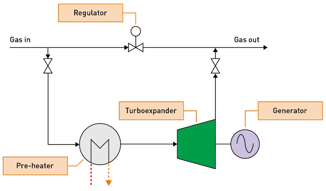
This document refers to the recovery of energy from high enthalpy gas. The Liquid power recovery turbines info sheet refers to the recovery of energy from liquids. A typical gas turboexpander system is illustrated in Figure 1.
There are two broad categories of turboexpander systems, namely turboexpander-generators and turboexpander-compressors, as described in American Petroleum Institute (API) 617. Many names are used to describe turboexpander-recompressors such as, expander-recompressors, companders, or simply turboexpanders. Turboexpander-generators can be further classified by the gearbox options of direct drive, external gearbox, or integrally geared. An integral gearing option provides the additional benefit of multi-staging, allowing multiple expander stages to be mounted on a single gearbox. In most cases, the turboexpander-generator unit can be completely skid-mounted to simplify transportation and reduce installation costs. The different types of turboexpander-generator configurations are as follows:
- Direct drive: the direct drive option, when feasible, eliminates the need for speed reduction, gearboxes, and associated equipment.
- External gearbox: expanders with an external gearbox feature patented bearings, with a common oil supply system for the complete package. The installed fleet ranges from 50 kW to 15 MW.
- Integral gearbox: this arrangement mounts the expander wheel directly on the high-speed pinion, eliminating the need for a high-speed coupling. Standard designs are available up to 15 MW.
- Multi-stage: high pressure ratios and/or high flow rates require the multi-stage arrangement. Standard expander-gear designs can accommodate up to four expanders on a common integral gearbox.
The expander principle relies on converting energy in the high-pressure gas into mechanical work or shaft power. This energy can be captured and used to drive a generator to produce electricity a compressor, or a pump, depending on the application. As gas flows from the high-pressure stream into the turboexpander, it spins the turbine, which is coupled to a generator that produces electricity. By replacing a conventional control valve or regulator with a turboexpander, the energy contained in the motive stream, that would otherwise be lost, can be used to drive an electric generator or mechanical equipment. Power output is proportional to pressure ratio, temperature, and the flow rate of the stream. The higher the flow rate and pressure differential, the higher the potential energy output. A complete control system, which includes inlet guide vane (IGV) controls, can be used to easily control an expander-compressor system.
The location of this technology within the facility should be carefully studied to optimize power generation potential and efficiency. Turboexpander systems can be in the following types of oil and gas facilities due to pressure and/or cooling requirements of the process:
- Dewpoint control (DPC)
- Pressure let-down
- Fluid catalytic cracking (FCC)
- Liquified petroleum gas (LPG)
- Natural gas liquids (NGL)
- Liquified natural gas (LNG)
- Nitrogen rejection
- Air separation facilities
- Organic Rankine cycles
The impact of the turboexpander needs to be considered in relation to the overall energy generation efficiency as generating additional power will reduce the power generation required or power imported by the facility. Understanding the turboexpander benefits on the overall process and utility supply network may be advantageous or lead to new constraints. For example, the additional power generated by the turboexpander may cause the main gas generators to run at minimum turndown or from the best efficiency point. Also, the additional cooling due to the expander can cause potential hydrate formations and hence require pre-heating before the gas enters the expander. This may offset the potential benefits of energy recovery from the turbo-expander.
In brownfield applications, the impact of additional power generation on the overall energy generation system would need to be evaluated. It is important to ensure that the power recovered from the turboexpander does not cause the power generation systems to be operated at minimum turndown (or at a significantly reduced efficiency), as this would reduce the overall efficiency.
Given the same gas inlet conditions and pressure drop, expansion through a turboexpander will yield a lower exhaust temperature than expansion through a Joule-Thomson valve (throttle valve). Several processes, such as dewpointing, refrigeration, and natural gas liquification, can benefit from the additional cooling that a turboexpander provides over the simple Joule-Thomson valve. In certain situations, turboexpander installations efficiently cope with this temperature loss. Turboexpanders can be coupled with a second power generator, such as a fuel cell or conventional fuel combusting generator. This secondary generator produces waste heat that can be used to offset the cooling effect of the turboexpander.
Incorporation of turboexpanders is best considered during design, as retrofitting will be difficult depending on brownfield considerations (such as space availability, complexity of site, location and so on). However, in specific locations where turboexpanders could be implemented later, provision for tie-ins and plot space considerations should be included considered in the design.
For upstream applications, the viability of the installation should be evaluated over the full life of the field, to account for the production profile in terms of flowrate, gas composition variability, and pressure profiles.
Reliability impacts should also be evaluated. In general, all expanders are installed with a bypass which aids start up and shutdown of the machines. The expander is added to increase efficiency, but the bypass is always available to keep the process running. Thus, the expected reliability impact on the production is small. The development and inclusion of proper controls and tuning are required to ensure the system is configured to handle transients, minimizing any impact on the overall operations.
Technology maturity
| Commercially available | Yes |
|---|---|
| Offshore viability | Yes |
| Brownfield retrofit | Yes |
Key metrics
| Range of application | Systems with a high gas enthalpy that need to be at a lower pressure/temperature downstream due to process requirements.
|
|---|---|
| Efficiency | Up to 90 per cent Defined by: Actual Power Recovery/Theoretical Power Recovery (either polytropic or isentropic efficiency which is defined by the basis of the Theoretical Power Recovery). |
| Energy KPIs |
|
| Guideline capital costs | Design, equipment, installation; cost dependent on project design and scale.
|
| Guideline operational costs | Potential to produce power from excess or stored energy will reduce total plant energy generation costs (operational costs), minus any related costs to maintain the turboexpander, minus the incremental design cost due to the application. This includes any reliability and availability requirements. Extra bypass may be required for control and to cater for unavailability of turboexpander. |
| Greenhouse gas (GHG) reduction potential | Power produced by turboexpanders can reduce on-site power generation or power import, thus lowering either scope 1 or scope 2 emissions. This improves overall plant energy efficiency, reducing overall GHG intensity. The benefit calculated should take into account the overall power generation efficiency. |
| Time to perform engineering and installation | 6 to 18 months Depends on if the equipment is off the shelf (6 months) or customized. Note that this could be a long-lead item depending on availability of the equipment. |
| Typical scope of work description | Work begins with collecting application data, which includes the flow and physical properties of the high-pressure stream (temperature, pressure), and the allowable discharge conditions. For power generation applications, it will be necessary to exercise due diligence with respect to the electrical infrastructure and loading. Although the turboexpander may be able to generate a significant portion of the electrical power needs, the power generation line-up may require some spinning reserve for process reliability and to manage large loads that may come online or offline. Sizing the turboexpander is typically done by vendors using proprietary software packages that optimize performance within the frame sizes available, given the process data above. |
Decision drivers
| Technical |
Specifically for upstream:
|
|---|---|
| Operational |
|
| Commercial |
|
| Environmental | Reduced environmental footprint by saving energy. Expanders are considered as green energy systems as they use recovered process energy to drive other equipment or generate electricity. |
Alternative technologies
Joule-Thomson, or let-down valves, can be used, but these are less efficient when trying to meet cooling requirements, and cannot recover any substantial energy.
For a dewpoint system, a mechanical refrigeration system can be used to achieve the temperature reduction instead of a turboexpander.
Operational issues/risks
- The flow rates may vary widely, which makes maintaining a steady power output difficult. This may introduce instability to the power system. The impact of this needs to be evaluated in relation to overall power generation system.
- Criticality to the overall system reliability - turboexpanders that are in services critical to unit operation may need additional features or facilities investment, for example, automatic bypasses with appropriate control strategies to achieve reliability targets
- The well head stream contains a mixture of gas, condensate, and water. Therefore, turboexpanders may not work efficiently at the well head with unprocessed gas.
- Pre-heating or injecting hydrate inhibitors, for example, monoethylene glycol before expansion, if there is potentially hydrate formation.
- Two phase inlet flow should be checked with the expander original equipment manufacturer (OEM) to confirm that droplet sizes are tolerable.
- When a turboexpander is directly coupled to a compressor, the operability of the process unit may become complex since both expansion and compression control systems are not completely independent of each other. This can be mitigated by properly designed and configured control systems (including inlet guide vane controls), as long as there are no side draws or side inlets between the expander and compressor sections. These are best configured in standalone trains.
- When selecting a turboexpander-compressor, one of the major decisions is between using oil lubricated bearings (OLB) or active magnetic bearings (AMB). If OLB is selected, it is important to consider how the process gas will degrade the lube oil, and the operating cost impact of ongoing lube oil loss to the process.
- For both turboexpander-generators and turboexpander-compressors, it is important to account for the need of seal gas, and dewpoint control of that seal gas. In the case of turboexpander-generators, the shaft seal will also have a primary and secondary vent that either needs to go to flare, atmosphere, or be recovered by a Vapour Recovery Unit. VRU. This will need to be included in the overall carbon footprint of the system.
Opportunities/business case
- While turboexpanders may only capture a few megawatts at a time, the widespread deployment of turboexpanders could contribute to a more efficient and greener energy system
- Even if the power obtainable at individual locations is not large compared to the conventional thermal power plants, by using turboexpanders on natural gas distribution systems, the sum of all locations can be substantial
Industry case studies
Turboexpander evaluation of potential in the Middle East [Reference 1]
Monthly natural gas flow data was taken from a single city gate station in the Middle East, and used in a computer simulation, to determine the potential for economical energy production, by installing a turboexpander in parallel with existing gas pressure reduction systems. Key metrics were natural gas flow rates, the amount of natural gas needed for preheating, and power produced by the system.
Baseline scenario
Use of throttle valves to reduce natural gas pipeline pressure at a city gate station.
Energy efficiency project activity
Installation of a turboexpander and generator in place of a throttle valve to reduce natural gas pipeline pressure when capturing associated energy production from natural gas expansion. The natural gas needed for preheating before expansion, and the variability of natural gas flow rates, were measured.
Performance specifications
- Turboexpander maximum power produced = 1.8 MW, 6000 MW-hr/year
- Turboexpander efficiency = 85%
References
- Ardali, E.K. and Heybatian, E. (2009). Energy regeneration in natural gas pressure reduction stations by use of gas turbo expander; evaluation of available potential in Iran.
Other resources
- Rahman, M. ‘Power generation from pressure reduction in the natural gas supply chain in Bangladesh.’ In Journal of Mechanical Engineering, Vol. ME 41, No. 2, December 2010. The Institution of Engineers, Bangladesh.